|
J456600 Oil Pump, Remove and Install (Y 17 DTL,
without AC, LHD)
Note: KM-6394 must be used from model year 04 instead of
KM-6169-1 .
|
1. Open bonnet
|
|
Caution!
On vehicles from model year 04 with ESP - the steering angle
sensor loses its basic adjustment each time the battery is
disconnected. It must be recalibrated.
2. Disconnect battery
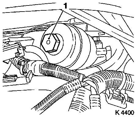
3. Remove oil filter element
- Place collecting basin underneath.
- Unscrew oil filter housing cover (1)
|
4. Remove oil dipstick guide tube
|
|
5. Loosen front right wheel
6. Raise vehicle
7. Remove front right wheel
8. Raise vehicle
|
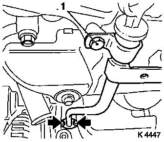
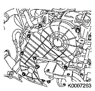
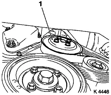
9. Remove ribbed V-belt cover
- Remove 3 bolts (1)
- Remove clip (arrow).
|
|
10. Drain engine oil
- Place collecting basin underneath.
- Remove drain bolt
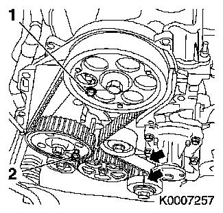
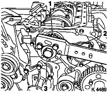
11. Install drain bolt
- Replace seal ring
- Tighten bolt (78.4 Nm / 57.9 lbf. ft.)
|
12. Detach exhaust system
Note: When removing
the centre muffler, a catalytic converter, an exhaust manifold, or
an exhaust manifold with catalytic converter, secure that portion
of the exhaust system remaining on the vehicle against uncontrolled
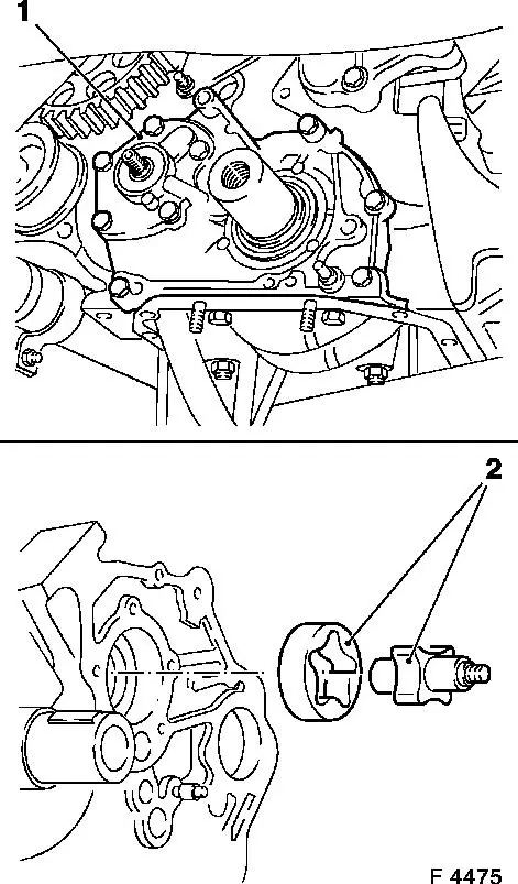
suspension.
For this purpose, the exhaust system portion including the flexpipe
may be fastened to the vehicle underbody using suitable means, e.g.
wire.
Caution!
Angular dislocations of the flexpipe as
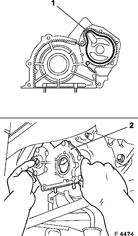
small as 5 to 10 degrees offset from the intended installation
position can already cause damage and subsequent complete failure
of the flexpipe.
- Detach rear muffler
- Release clamp
- Remove from rubber dampers
- Detach front exhaust pipe
|
|
13. Remove exhaust system
- Remove exhaust system
- Remove from 2 damping rings
- Note! 2. mechanic
14. Remove oil dipstick guide tube
|
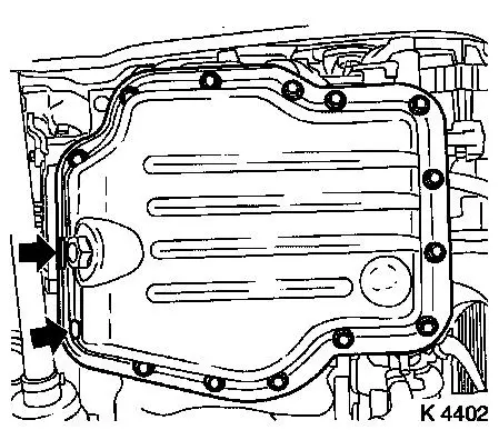
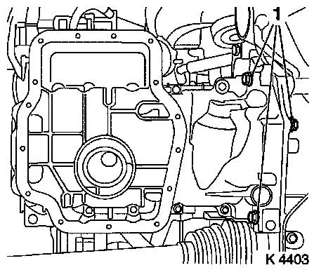
15. Detach lower part of oil pan
- Remove 15 bolts
- Detach with KM-J-37228
|
|
|
16. Detach upper part of oil pan
- Remove 14 bolts
- Note! Note dissimilar bolt lengths
- Remove 3 bolts (1)
- Remove 2 nuts
- Note! Use wide spatulas
|
|
17. Remove oil dipstick guide tube
|
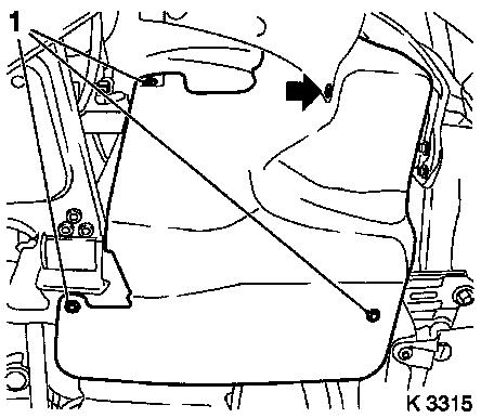
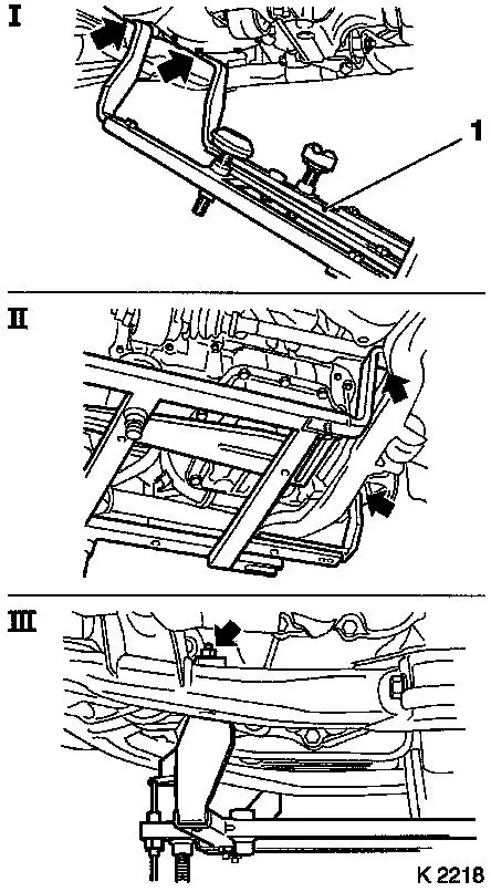
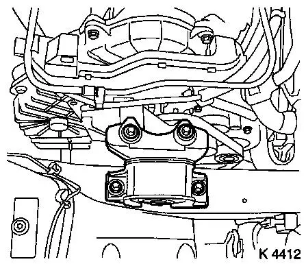
18. Attach KM-6169 (1)
- Place left of KM-6169 onto front axle body (arrows, illus.
I)
- Note! Guide pin must be seated in bore in front axle body
- Attach both right holders on the front axle body (arrows,
Illus. II).
- Note! Guide pin must be seated in bore in front axle body
(arrow, Illus. III)
- Tighten bolts
|
|
|
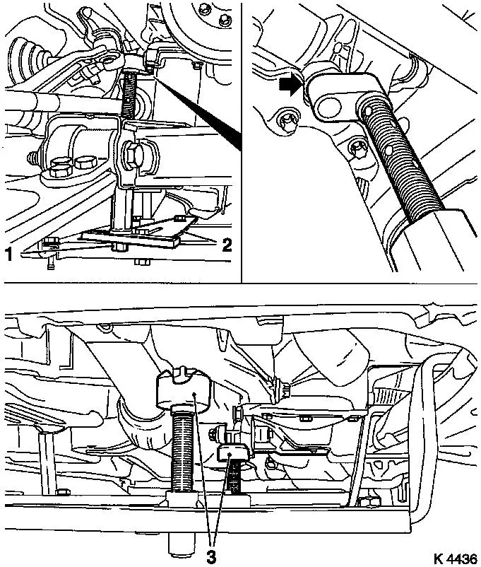
19. Install support
- To KM-6169
- Adjust bracket (2) for support
- Screw on nut (1)
|
|
20. Adjust supports
- Transmission side
- Note! Turn spindles until the mounts (3) are positioned at the
guide journals free of play
- Engine timing side
- Insert journal of the support in the bore of the cylinder block
without play (arrow)
- Tighten nuts (1)
21. Lower vehicle
|
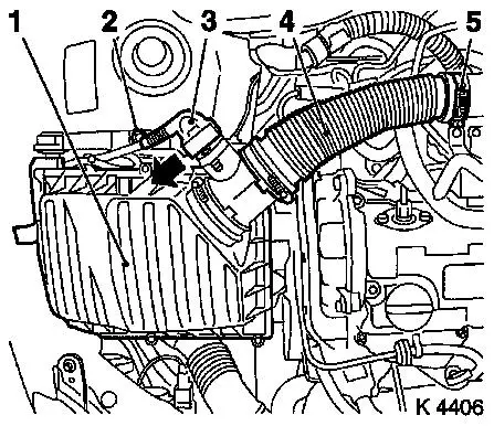
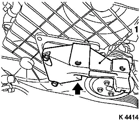
22. Remove air cleaner housing (1)
- Remove wiring harness plug for hot film mass air flow meter
(3)
- Release in direction of arrow
- Remove air intake hose (4)
- Remove bolt (2)
|
|
|
23. Remove right engine damping
block
|
|
24. Detach alternator wiring
harness
- Disconnect wiring harness plug
- Unscrew nut
|
25. Remove wiring trough (1)
- Unclip vacuum lines (2)
- Unclip wiring trough
- Remove bolt (3)
|
|
|
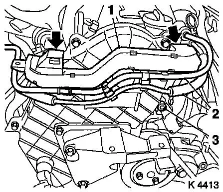
26. Loosen upper part of toothed belt
cover
- Remove 8 bolts
- Note! Note dissimilar bolt lengths
|
|
|
27. Detach right engine bracket (1)
- Remove 3 bolts
- Remove right engine bracket, right engine bracket adapter,
upper part of toothed belt cover
|
|
28. Raise vehicle
|
29. Loosen coolant pump ribbed V-belt
pulley (1)
|
|
|
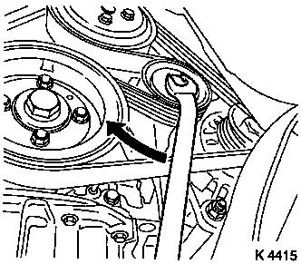
30. Remove ribbed V-belt
- Tension ribbed V-belt tensioner in direction of arrow
- Note! Mark running direction
|
|
31. Detach coolant pump ribbed V-belt
pulley
|
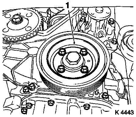
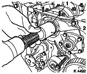
32. Remove torsional vibration damper
(1)
|
|
|
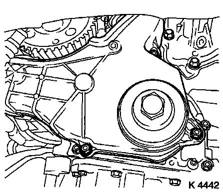
33. Detach lower part of toothed belt
cover
|
|
|
34. Set 1st cylinder to TDC
- Turn crankshaft evenly until TDC-fixing bolts can be
inserted
- Camshaft gear (M6) (1)
- Injection pump gear (M8) (2)
- Note! The mark on toothed belt drive gear must align with lug
on oil pump cover (arrows)
|
|
35. Lower vehicle
|
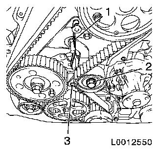
For toothed belt tension roller with
leaf spring:
- loosen toothed belt tensioner
- Screw in bolt (M10) in lower bore (3) of toothed belt
tensioner
- Loosen bolt (2)
- Remove tension spring (1)
|
|
|
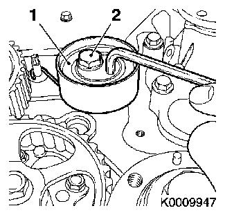
For toothed belt tension roller with
spiral spring:
- Loosen toothed belt tension roller (1)
- Rotate toothed belt tension roller anticlockwise approx.
90°
- Tighten bolt (2)
|
|
37. Remove toothed belt
- Note! Mark running direction
|
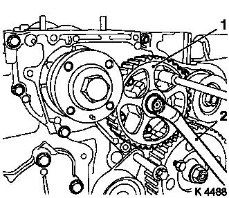
38. Remove oil pump drive gear (1)
- Unscrew nut
- Note! Counterhold using socket spanner (2)
|
|
39. Raise vehicle
|
40. Turn crankshaft
- Turn crankshaft to approx. 60° before TDC on power stroke
of 1st cylinder
|
|
41. Attach KM-662-C (2)
42. Detach toothed belt drive pulley
(1)
- Remove bolt (3)
- Counterhold using KM-662-C
- Remove toothed belt drive gear
- Remove woodruff key
|
43. Remove oil pump cover (1)
- Remove 9 bolts
- Note! Note dissimilar bolt lengths
- Remove inner and outer rotors (2)
|
|
|
44. Clean sealing surfaces
- Cylinder block, oil pump cover
|
|
45. Inspect components
- Oil pump cover, cylinder block, inner rotor, outer rotor
46. Remove oil pump sealing ring
(2)
- Lever out seal ring
- Caution! Do not damage sealing surfaces
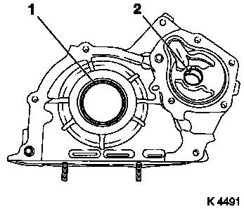
47. Remove crankshaft front seal ring
(1)
- Lever out seal ring
- Caution! Do not damage sealing surfaces
|
48. Install oil pump seal ring
- Lightly coat sealing lip of new seal ring with silicone grease
(white)
- Drive in until flush using KM-657
|
|
49. Install oil pump cover (2)
- Insert inner and outer rotor
- Clean thread.
- Replace gasket (1)
- Apply adhesive sealing compound (black) (shaded area)
- Attach oil pump cover
- Tighten bolts (9.8 Nm / 7.2 lbf. ft.)
|
50. Install crankshaft front seal ring
(1)
- Lightly coat sealing lip of new seal ring with silicone grease
(white)
- Drive in until flush using KM-656 (2)
|
|
51. Install toothed belt drive gear
- Install sheet metal panel
- Insert toothed belt drive gear in place
- Tighten bolt (198 Nm / 146 lbf. ft.)
52. Remove KM-662-C
53. Lower vehicle
54. Install oil pump drive gear
- Note! Observe installation position
- Tighten nut (44.1 Nm/32.6 lbf. ft.)
55. Turn crankshaft
- Turn crankshaft to 1st Cylinder TDC
56. Install toothed belt
Note: Toothed belt
must be taut from toothed belt drive gear via oil pump drive gear
and injection pump drive gear
- For toothed belt tension roller with leaf spring:
- Unscrew TDC-fixing bolt
- Rotate crankshaft 60° against direction of engine
rotation
- Tighten bolt of toothed belt tension roller
- For toothed belt tension roller with spiral spring 49 Nm
- For toothed belt tension roller with leaf spring 38.2 Nm
57. For toothed belt tension roller with leaf spring: unscrew
bolt (M10) from lower bore of toothed belt tensioner
|
58. Set 1st cylinder to TDC of
combustion stroke
- Turn crankshaft approx. 780° in direction of engine
rotation
- Turn crankshaft evenly until TDC-fixing bolts can be
inserted
- Camshaft gear (M6) (1)
- Injection pump gear (M8) (2)
- Note! The mark on toothed belt drive gear must align with lug
on oil pump cover (arrows)
- Unscrew TDC-fixing bolts
|
|
59. Unscrew lower fastening bolt of toothed belt tension
roller
60. Attach lower part of toothed belt
cover
- Tighten bolts (9.8 Nm / 7.2 lbf. ft.)
61. Attach right engine bracket
- Insert lower bolt
- Into right engine bracket and right engine bracket adapter
- Insert right engine bracket, right engine bracket adapter,
upper part of toothed belt cover
- Install 2 upper bolts
- Tighten 3 bolts (40 Nm / 29.5 lbf. ft.)
62. Install right engine damping
block
- To side member
- Tighten bolts (40 Nm / 29.5 lbf. ft.)
- On engine bracket
- Tighten bolts (60 Nm/44 lbf. ft + 30° + 15°.)
63. Fasten upper part of toothed belt
cover
- Tighten bolts (9.8 Nm / 7.2 lbf. ft.)
- Note! Note dissimilar bolt lengths
64. Attach coolant pump ribbed V-belt
pulley
65. Raise vehicle
66. Install torsional vibration
damper
- Tighten bolts (19.6 Nm / 14.5 lbf. ft.)
67. Install ribbed V-belt
- Note! Observe running direction and installation position
- Release ribbed V-belt tensioner
68. Fasten coolant pump ribbed V-belt
pulley
- Tighten bolts (9.8 Nm / 7.2 lbf. ft.)
69. Detach support
70. Remove KM-6169
71. Clean sealing surfaces
- Cylinder block, upper part of oil pan, lower part of oil
pan
72. Install upper part of oil pan
- Apply sealing compound (grey)
- Caution! The application of silicone sealing compound (grey)
and installation of lower part of oil pan including torque test
must be performed within 10 minutes!
- Tighten bolts (9.8 Nm / 7.2 lbf. ft.)
- Tighten nuts (9.8 Nm / 7.2 lbf. ft.)
- Bolts (M10) (40 Nm / 29.5 lbf. ft.)
73. Attach lower part of oil pan
- Apply sealing compound (grey)
- Tighten bolts (9.8 Nm / 7.2 lbf. ft.)
74. Insert front exhaust pipe
- Into isolator rings
- Note! 2. mechanic
75. Fasten front exhaust pipe
- Replace gasket
- Tighten 2 nuts (65 Nm / 47.9 lbf. ft.)
76. Insert rear muffler
77. Fasten rear muffler
78. Attach ribbed V-belt cover
- Install 3 bolts
- Install clip
79. Lower vehicle
80. Install right front wheel
81. Lower vehicle
82. Fasten right front wheel
- Tighten bolts (110 Nm / 81 lbf. ft.)
83. Insert oil dipstick guide tube
84. Raise vehicle
85. Install oil dipstick guide tube
- Tighten bolts (9.8 Nm / 7.2 lbf. ft.)
86. Lower vehicle
87. Install oil dipstick guide tube
88. Attach wiring trough
- Clip-in wiring trough
- Clip in vacuum lines
- Tighten bolt
89. Attach alternator wiring
harness
- Connect wiring harness plug.
- Tighten nuts
90. Install air cleaner housing
- Tighten bolt
- Fasten air intake hose.
- Connect wiring harness plug to hot film mass air flow
meter
91. Connect battery
92. Calibrate steering angle sensor
Note: Rotate the
steering wheel one time from its right-hand to its left-hand
stop.
93. Top up engine oil
- Observe specified engine oil quantity
- Start engine and allow to run until oil pressure telltale
extinguishes.
- Check engine oil level, if necessary correct.
94. Program volatile memories
95. Close bonnet
|
