|
Camshaft Seal Ring, Replace (Z 17 DTH, with AC,
LHD)
 Remove Remove
Important: On vehicles as of
model year 04 with ESP - every time the battery is disconnected,
the steering angle sensor loses its basic setting. It must be
recalibrated.
|
| 2. |
Disconnect battery
|
| 3. |
Detach front right wheel
|
| 5. |
Remove right front wheel
|
| 7. |
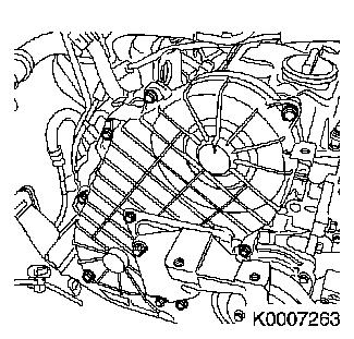
Remove ribbed V-belt cover
|
|
|
| 8. |
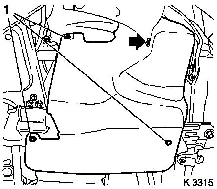
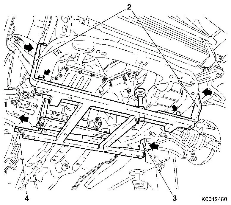
Attach KM-6394
| • |
Position KM-6394 (1) at the front on
the front axle body
Note: Both locating
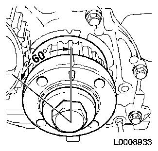
pins (arrows) must be seated in the holes in the front axle
body
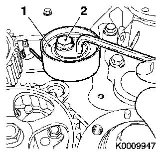
|
| • |
Push front bracket (2) in the direction of the arrow
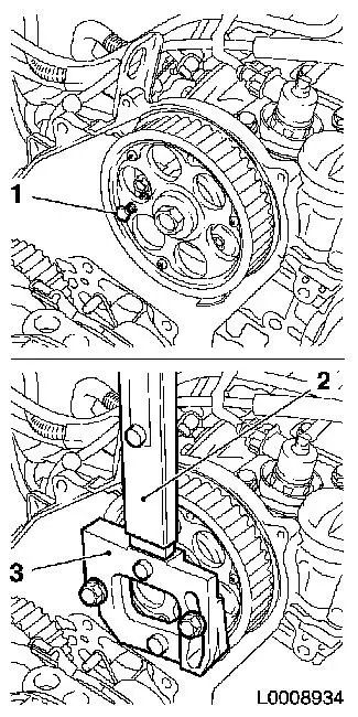
|
| • |
Place rear bracket (4), right hand side, on front axle body
|
| • |
Attach rear bracket (3), left hand side
|
|
|
|
|
| 9. |
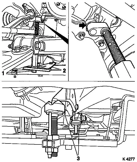
Install support
| • |
On KM-6394
| – |
Adjust bracket (2) for support
|
|
|
| 10. |
Adjust 3x support
| • |
Transmission side
Note: Turn spindles
until mounts (3) are positioned at guide journals free of play
|
| • |
Engine timing side
| – |
Insert journal of the support in the bore of the cylinder block
free of play (arrow)
|
|
|
|
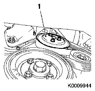
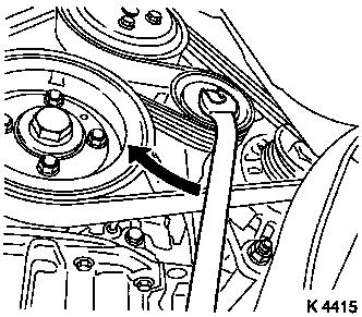
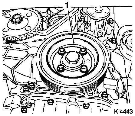
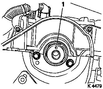
| 11. |
Loosen coolant pump ribbed V-belt pulley (1)
|
|
|
| 12. |
Remove ribbed V-belt
| • |
Tension ribbed V-belt tensioner in direction of arrow
| – |
Use KM-913-A
Note: Mark running
direction.
|
|
|
|
|
| 13. |
Detach coolant pump ribbed V-belt pulley
|
| 14. |
Detach starter wiring harness
| • |
Electrically disconnect starter
|
| • |
Disconnect wiring harness plug of fuel pressure sensor
|
|
| 16. |
Remove air cleaner housing
|
|
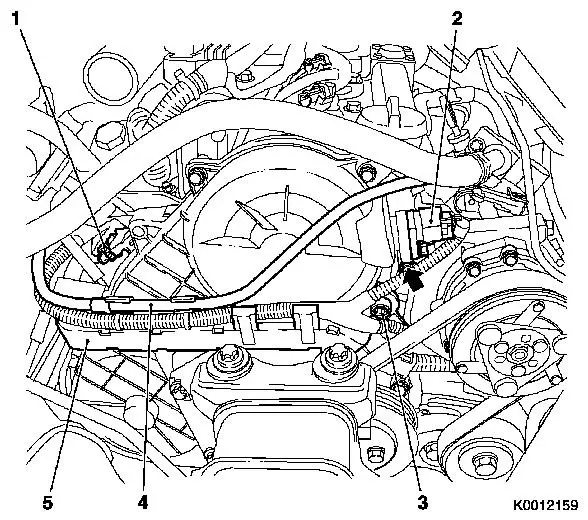
| 17. |
Remove wiring trough
| • |
Unclip wiring trough (5)
|
| • |
Disconnect 2 wiring harness plugs
| – |
Charge pressure sensor (1)
|
|
|
| 18. |
Remove camshaft sensor
|
|
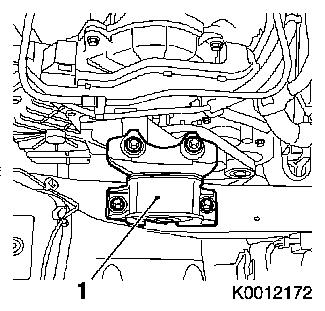
| 19. |
Remove right engine damping block (1)
|
|
|
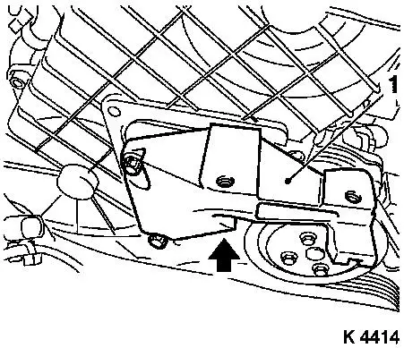
| 20. |
Detach right engine bracket (1)
| • |
Unscrew 3 bolts
Note: Lower bolt cannot
be removed
|
| • |
With right engine bracket adapter
|
|
|
|
| 21. |
Remove upper toothed belt cover
Important: Take care not to
damage the increment counter on the camshaft sprocket when removing
the upper toothed belt cover
|
| • |
Unscrew 8 bolts
Note: Note dissimilar
bolt lengths
|
|
|
|
| 23. |
Remove torsional vibration damper (1)
|
|
|
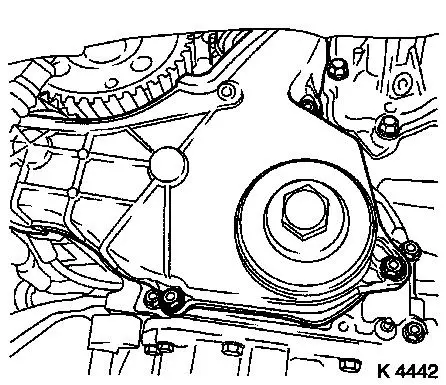
| 24. |
Detach lower part of toothed belt cover
|
|
|
| 25. |
Remove right engine bracket
|
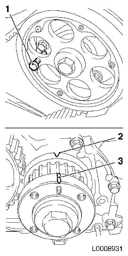
| 26. |
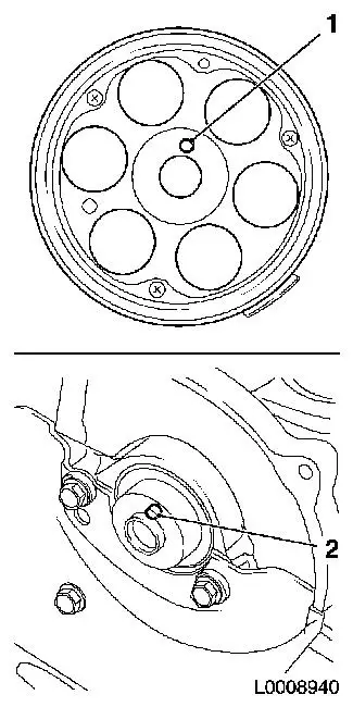
Set 1st cylinder to TDC
| • |
Turn crankshaft evenly until TDC fixing bolt (1) can be screwed
in
Note: Mark (3) on
toothed belt drive gear must align with mark (2) on oil pump
cover
|
|
|
|
| 27. |
Loosen toothed belt tension roller (1)
| • |
Loosen bolt of toothed belt tension roller (2)
|
| • |
Rotate toothed belt tension roller anticlockwise approx.
90°
|
| • |
Tighten bolt of toothed belt tension roller
|
|
| 28. |
Remove toothed belt
Note: Mark running
direction.
|
|
|
| 29. |
Turn crankshaft
| • |
Rotate crankshaft 60° against direction of engine
rotation
|
|
|
|
| 31. |
Detach camshaft pulley
| • |
Unscrew TDC fixing bolt (1)
|
| • |
Remove bolt
| – |
Use KM-956-1 (2) in combination with
KM-6156 (3)
|
|
|
|
|
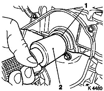
| 32. |
Remove camshaft seal ring
Important: Do not damage sealing
surfaces
|
| • |
Lever out seal ring (1)
|
|
|
|
 Install
| 33. |
Install camshaft seal ring
| • |
Drive in seal ring with KM-657 (2)
until flush
|
|
|
|
Warning: The different camshaft
sprockets (with different part numbers) have different torques for
the camshaft sprocket bolt.
|
| 34. |
Attach camshaft sprocket with part number 97320335
| • |
Camshaft journal (2) must engage in the bore in the camshaft
sprocket (1)
|
| • |
Use KM-6347 in combination with KM-956-1
|
| • |
Install TDC-fixing bolt
|
|
| 35. |
Attach camshaft sprocket with part number 98021306
| • |
Camshaft journal (2) must engage in the bore in the camshaft
sprocket (1)
|
| • |
Use KM-6347 in combination with KM-956-1
|
| • |
Install TDC-fixing bolt
|
|
|
|
| 37. |
Turn crankshaft
| • |
Set crankshaft to 1st cylinder TDC
Note: Mark (3) on
toothed belt drive gear must align with the mark (2) on oil pump
cover
|
| • |
Block camshaft using TDC fixing bolt (1)
|
|
|
|
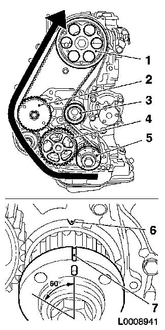
| 39. |
Install toothed belt
Note: TDC locking bolt
must be installed in the camshaft sprocket and marking (6) and (7)
must align.
| • |
Position toothed belt
| – |
Toothed belt must be tensioned in the direction of the arrow
from the toothed belt drive gear (5) via the oil pump drive gear
(4), via the high pressure pump drive gear (2) to the camshaft
sprocket (1)
|
|
| • |
Loosen toothed belt tension roller (3)
|
| • |
Remove TDC locking bolt
|
| • |
Rotate crankshaft 60° against direction of engine
rotation
|
| • |
Tighten toothed belt tension roller 38Nm
|
|
|
|
| 40. |
Timing, Check
| • |
Turn crankshaft approx. 780° in direction of engine
rotation
|
| • |
Mark on toothed belt drive gear (3) must align with cast lug
(2) on oil pump cover
|
| • |
Screw in TDC fixing bolt (1)
Note: If the TDC fixing
bolt cannot be screwed in, basic adjustment must be repeated.
|
| • |
Unscrew TDC-fixing bolt
|
|
|
|
| 42. |
Attach right engine bracket
| • |
Insert lower bolt
| – |
Into right engine bracket and right engine bracket adapter
|
|
| • |
Fit right engine bracket with adapter
|
|
| 43. |
Attach lower part of toothed belt cover
|
| 45. |
Install upper toothed belt cover
| • |
Tighten 8 bolts 9.8 Nm
Note: Note dissimilar
bolt lengths
|
|
| 46. |
Fasten right engine bracket
| • |
Tighten 2 upper bolts 40 Nm
|
|
| 47. |
Install camshaft sensor
|
| 48. |
Attach wiring trough
| • |
Connect 2 wiring harness plugs
|
|
| 49. |
Install right engine damping block
| • |
On engine bracket
| – |
Tighten 2 bolts 60 Nm + 30° +
15°
|
|
|
| 51. |
Fasten right engine bracket
| • |
Tighten lower bolt 40 Nm
|
|
| 52. |
Attach coolant pump ribbed V-belt pulley
|
| 53. |
Install torsional vibration damper
| • |
Tighten 4 bolts 19.6 Nm
|
|
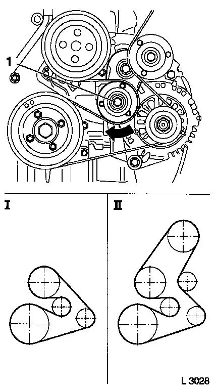
| 54. |
Install ribbed V-belt
Note: Observe running
direction and installation position
| • |
Release tension from ribbed V-belt tensioner (1)
| – |
I Ribbed V-belt without AC
|
| – |
II Ribbed V-belt with AC
|
|
|
|
|
| 55. |
Fasten coolant pump ribbed V-belt pulley
|
| 58. |
Attach starter wiring harness
| • |
Electrically connect starter
|
| • |
Connect fuel pressure sensor wiring harness plug
|
|
| 59. |
Attach ribbed V-belt cover
|
| 61. |
Attach front right wheel
|
| 63. |
Fasten right front wheel
|
| 64. |
Install air cleaner housing
|
| 66. |
Calibrate steering angle sensor
| • |
Turn on ignition
Note: Turn the steering
wheel once from the right stop to left stop.
|
|
| 68. |
Program volatile memory
|
|
