|
Checking engine pressure loss
 Remove Remove
| 3. |
Remove air intake hose
|
|
| 4. |
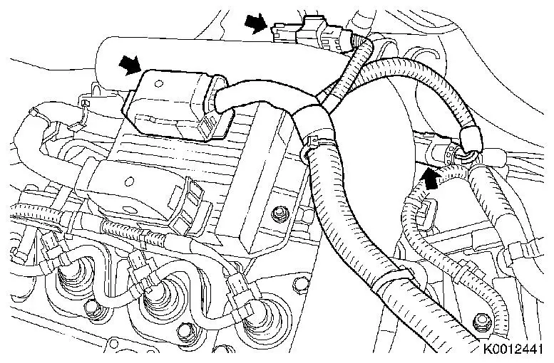
Remove engine management wiring harness
| • |
Disconnect 3 wiring harness plugs (arrows)
|
|
|
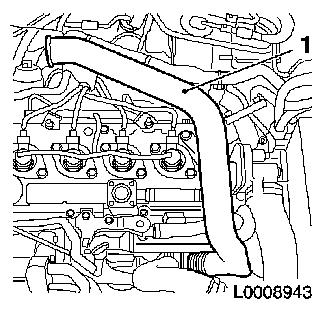
| 5. |
Loosen air intake pipe (1)
| • |
Remove engine vent hose
|
|
|
|
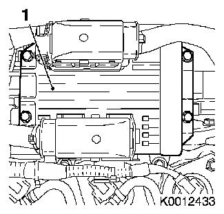
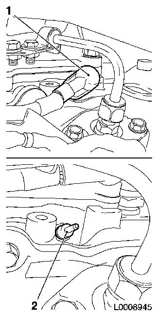
| 6. |
Remove engine control unit (1)
| • |
Release wiring harness plug in direction of arrow
|
|
|
|
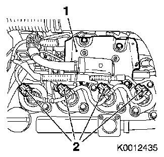
| 7. |
Disconnect 4 wiring harness plugs, injector (2)
|
| 8. |
Detach engine control unit bracket (1)
|
|
|
| 9. |
Disconnect 4x wiring harness plug, sheathed glow plug (1)
|
| 10. |
Remove 4x sheathed glow plug (2)
|
|
|
| 11. |
Raise vehicle all the way
|
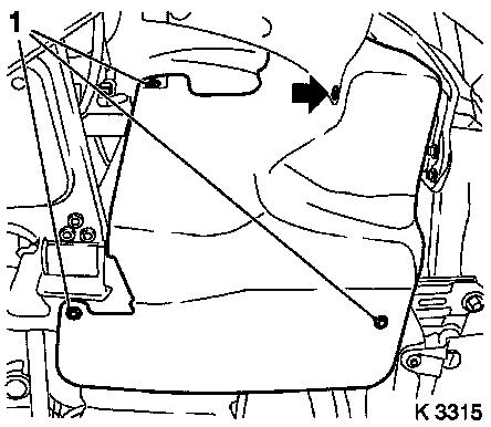
| 12. |
Remove right engine splash guard
| • |
Remove body-bound rivet (arrow)
|
|
|
|
| 13. |
Remove coolant compensation tank cap, oil filler port closure
cap and oil dipstick
|
 Inspect
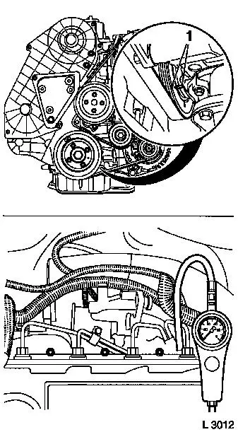
| 14. |
Set crankshaft to "1st cylinder TDC" following direction of
engine rotation
| • |
The markings (1) must align
Note: The cams of 1st
cylinder must face up - Cam position can be checked via the oil
filler port. If 1st cylinder cams do not face up, turn the
crankshaft one revolution to "1st cylinder TDC".
|
|
| 15. |
Affix guide marking to torsional vibration damper
Note: Guide marking
must be exactly 180° across from TDC marking
|
| 16. |
Attach pressure loss tester
| • |
Together with connector KM-6367
|
| • |
Calibrate pressure loss tester
Note: Follow
manufacturer's instructions
|
|
|
|
| 17. |
Engage 4th gear; apply handbrake
|
| 18. |
Check 1st cylinder pressure loss
| • |
Max. pressure difference between individual cylinders - approx.
10 %
|
| • |
Pressure loss per cylinder should not exceed 25 %
|
| • |
Check the following for air discharge to locate any damage:
| – |
Coolant compensation tank, dipstick guide tube
|
|
|
| 19. |
Detach pressure loss tester
| • |
Together with connector KM-6107
|
|
| 20. |
Repeat pressure loss test for 3rd, 4th and 2nd cylinder
Note: Turn crankshaft
180° to guide marking or TDC marking
|
 Install
| 21. |
Fit coolant compensation tank cap, oil filler port closure cap
and oil dipstick
|
| 22. |
Install 4 sheathed glow plugs 17.5
Nm
|
| 23. |
Connect 4x injector wiring harness plug
|
| 24. |
Attach engine control unit bracket
|
| 25. |
Connect 4x injector wiring harness plug
|
| 26. |
Fit engine control unit
| • |
Connect wiring harness plug
|
|
| 27. |
Fasten air intake pipe
|
| 28. |
Attach engine management wiring harness
| • |
Connect 3 wiring harness plugs
|
|
| 29. |
Install air intake hose.
|
| 32. |
Calibrate steering angle sensor
| • |
Turn on ignition
Note: Rotate the
steering wheel one time from its right-hand to its left-hand
stop.
|
|
| 33. |
Program volatile memory
|
|
