|
Remove and install all pistons with con-rods (Z 10
XE, Z 10 XEP, without air conditioning, LHD)
Note: On vehicles as
of model year 04 with ESP - every time the battery is disconnected,
the steering angle sensor loses its basic setting. It must be
recalibrated.
 Remove Remove
| 1. |
Open bonnet
Note: KM-6394 must be used as of model year 04 instead of
KM-6169-1 .
|
| 3. |
Drain coolant
Note: With model
variant "ECO" - remove lower engine compartment cover 
| • |
Place collecting basin underneath.
|
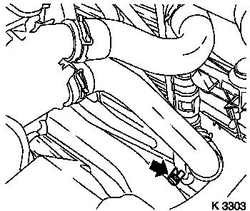
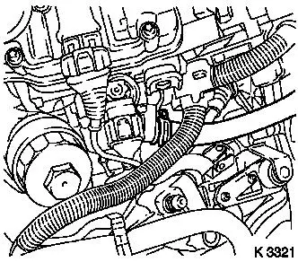
| • |
Open drain bolt (arrow)
|
|
|
|
| 4. |
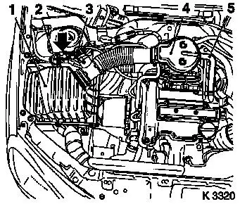
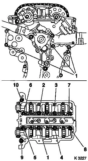
Remove air cleaner housing (1)
| • |
Disconnect 2 wiring harness plugs
| – |
Hot film mass air flow sensor (3), tank vent valve (2)
|
|
| • |
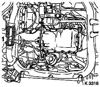
Remove suction pipe (4)
| – |
Detach engine vent hose (5)
|
|
| • |
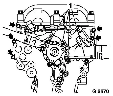
On Z 10 XEP: Remove air intake hose
|
|
|
|
| 5. |
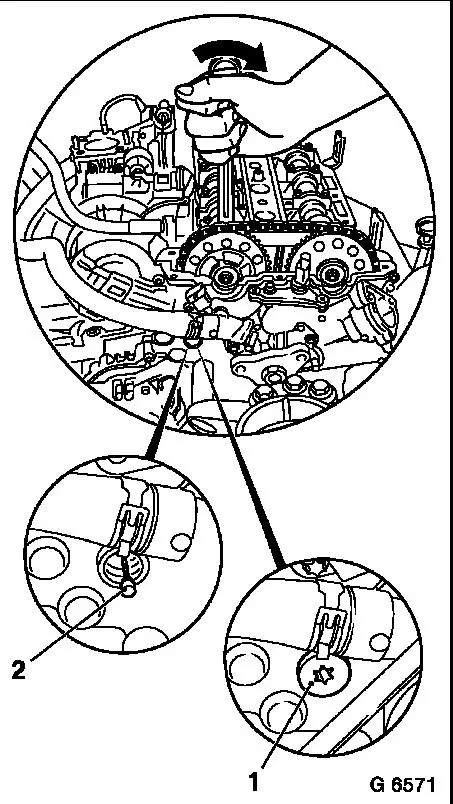
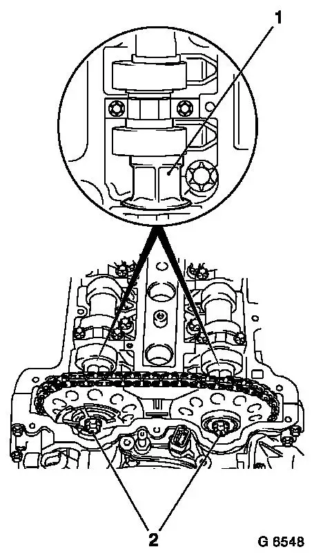
Remove intake pipe (1)
|
|
|
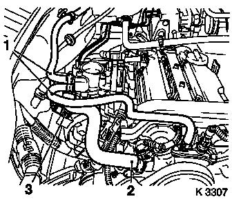
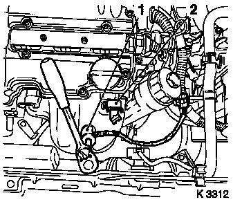
| 6. |
Remove preheater hoses for throttle body (1)
| • |
Detach from throttle valve pipe, coolant pump
|
|
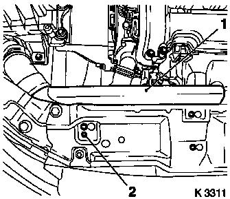
| 7. |
Detach heater supply hose (2) from coolant pump
|
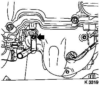
| 8. |
Remove brake servo vacuum line (3)
|
|
|
| 9. |
Detach heater return hose from exhaust gas recirculation
coolant flange
|
|
|
Important: Observe safety
precautions and national regulations
|
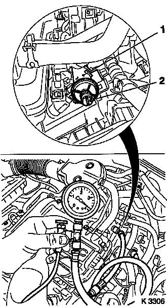
| 10. |
Reduce fuel pressure
| • |
Unscrew test connection protective cap (2)
Note: Test connection
for Z 10 XEP at upper fuel rail
|
| • |
Fit KM-J-34730-91 to fuel rail
(1)
|
|
|
|
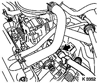
| 11. |
Detach fuel line (arrow) with KM-796-A
|
|
|
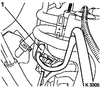
| 12. |
Detach fuel evaporation hose (1)
| • |
Detach hose from intake manifold and set to one side
|
|
|
|
|
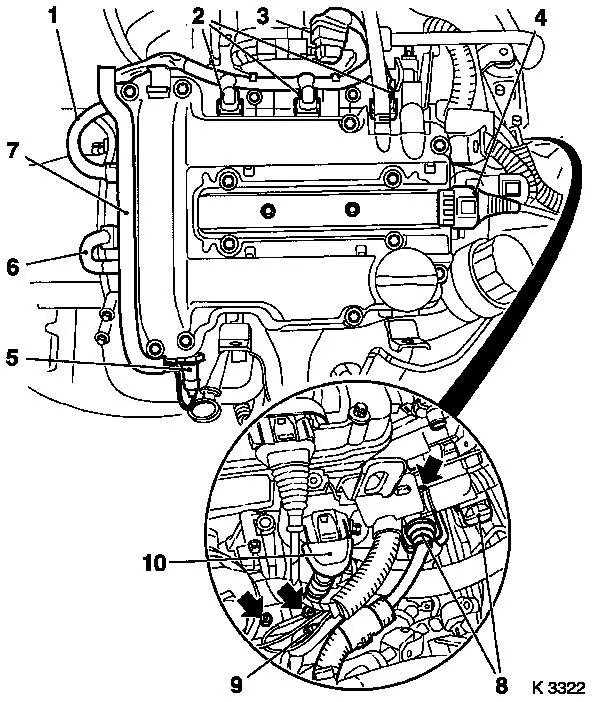
| 13. |
Disconnect engine management wiring harness plug
| • |
On Z 10 XEP: Remove fuel rail cover
|
| • |
Disconnect 11x wiring harness plugs
| – |
Oil pressure switch (5), coolant temperature sensor (6),
camshaft sensor (1), injectors (2), throttle valve adjuster (3),
engine control unit (8), combination plug (9), exhaust gas
recirculation valve (10), ignition module (4)
|
|
| • |
Detach 3x ground cables (arrows)
|
| • |
Unclip wiring trough (7)
|
| • |
Set wiring harness to one side
|
|
|
Important: Angular dislocations
of the flexpipe as small as 5 to 10 degrees offset from the
intended installation position can cause damage and subsequent
complete failure of the flexpipe.
|
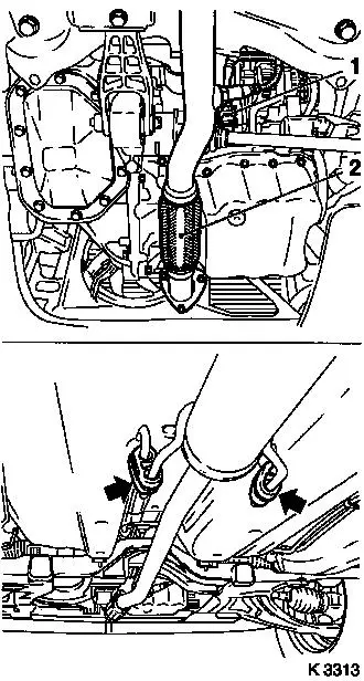
| 15. |
Loosen exhaust system
Note: When removing the
centre muffler, a catalytic converter, an exhaust manifold or an
exhaust manifold with catalytic converter, the exhaust system piece
remaining in the vehicle must be secured to prevent it sagging
uncontrollably. The exhaust system piece with the flex pipe inside
it can be fastened to the vehicle underbody with suitable materials
such as wire.
| • |
Detach oxygen sensor (catalytic converter control) wiring
harness plug (1)
|
| • |
Detach 2x damper rings (arrows)
|
| • |
Unscrew front exhaust pipe (2)
|
| • |
Tie front exhaust pipe to left front axle body
|
|
|
|
| 16. |
Drain engine oil
| • |
Place another collecting basin underneath
|
|
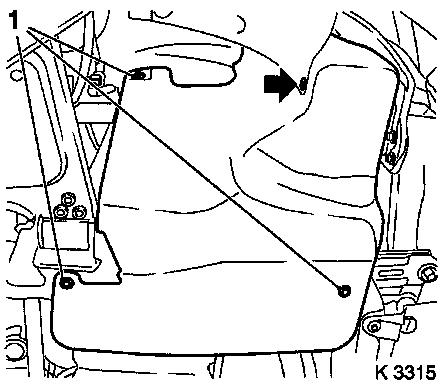
| 17. |
Remove ribbed V-belt cover
|
|
|
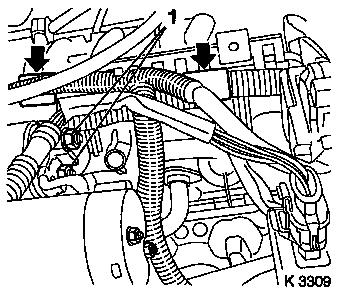
| 18. |
Remove wiring harness for engine management
| • |
Detach starter wiring harness
|
| • |
Open 2x brackets (arrows)
|
|
|
|
| 19. |
Install engine oil drain bolt
|
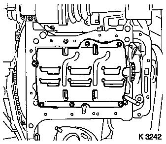
| 20. |
Remove oil pan
| • |
Crankshaft bearing bridge
|
|
|
|
| 21. |
Detach oil baffle plate
|
|
|
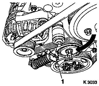
| 22. |
Remove ribbed V-belt
| • |
Tension ribbed V-belt tensioner in direction of arrow with
KM-6131
|
| • |
Release ribbed V-belt tensioner
|
|
|
|
| 23. |
Attach KM-6169-2 to transmission
|
|

|
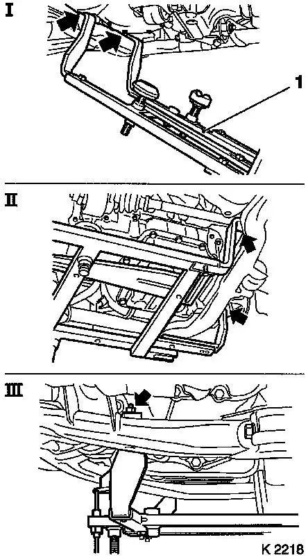
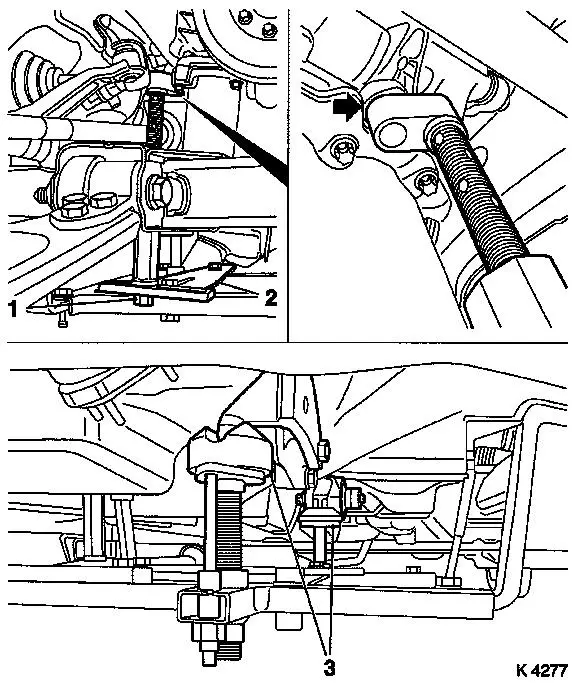
| 24. |
Attach KM-6169 (1)
| • |
Attach KM-6169 to left of front axle
body (arrows, illus. I)
| – |
Guide pin must be seated in bore in front axle body
|
|
| • |
Attach both right holders on the front axle body (arrows,
Illus. II).
| – |
Guide pin must be seated in bore in front axle body (arrow,
Fig. III)
|
|
|
|
|
|
| 25. |
Install support
| • |
An KM-6169
| – |
Adjust bracket (2) for support
|
|
|
| 26. |
Adjust supports
| • |
Transmission side
| – |
Turn spindles until mounts (3) are positioned at guide journals
free of play
|
|
| • |
Engine timing side
| – |
Insert journal of the support in the bore of the cylinder block
without play (arrow)
|
|
|
|
| 27. |
Loosen right engine bracket
|
|
|
| 29. |
Remove oil dipstick guide tube
| • |
Turn oil dipstick guide tube towards the front
|
|
|
|
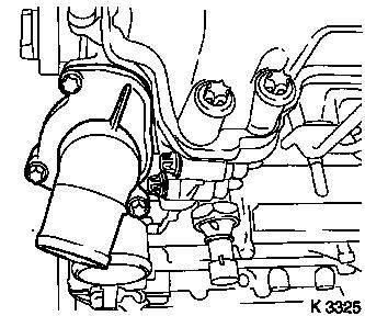
| 30. |
Remove heated oxygen sensor for mixture regulation
| • |
Disconnect wiring harness plug
|
| • |
Unscrew carefully using KM-6129
(1)
|
|
| 31. |
Detach left engine transport shackle (2)
|
| 32. |
Remove exhaust manifold heat shield
|
|
|
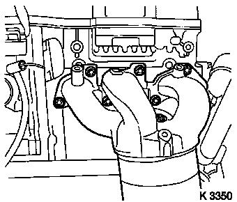
| 33. |
Remove exhaust manifold
|
|
|
| 34. |
Remove oil filter housing cover
|
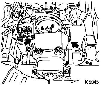
| 35. |
Remove oil filter housing (1)
| • |
Place another collecting basin underneath
|
|
|
|
| 36. |
Remove upper radiator hose
|
| 37. |
Remove right engine bracket
| • |
Remove right engine damping block
|
| • |
Remove engine bracket
| – |
Unscrew 2 bolts (arrows)
|
|
|
| 38. |
Remove ribbed V-belt
Note: Mark running
direction.
|
|
|
| 39. |
Remove coolant pump ribbed V-belt pulley
|
| 40. |
Detach coolant connection
|
|
|
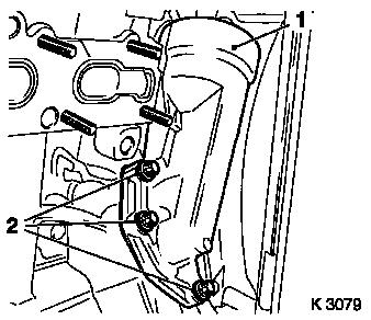
| 41. |
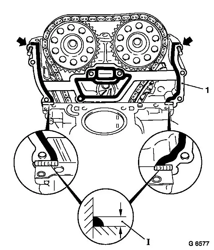
Remove timing case fastening bolts
| • |
Timing case
| – |
Unscrew 5 bolts (arrows)
|
|
|
|
|
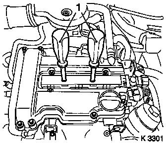
| 42. |
Remove ignition module
| • |
Remove ignition module cover
|
| • |
Extract using KM-6009 (1)
Note: Do not tilt
|
|
| 43. |
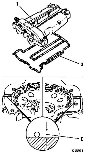
Remove cylinder head cover
| • |
Detach engine vent hose
|
|
|
|
|
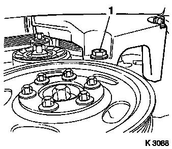
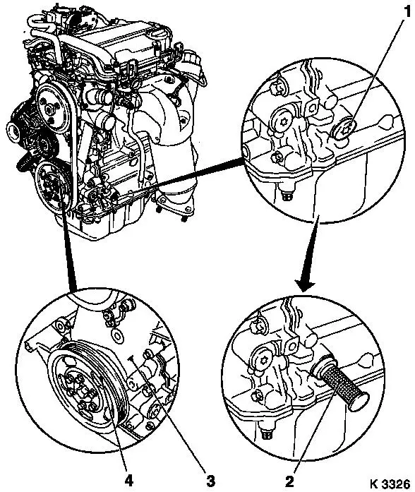
| 44. |
Set no.1 cylinder to TDC
| • |
Remove closure bolt for crankshaft bearing bridge (1)
|
| • |
Insert KM-952 (2)
Note: Crankshaft belt
pulley (4) must line up with lug (3) on timing case
| – |
Turn crankshaft uniformly until KM-952 engages
|
|
|
|
|
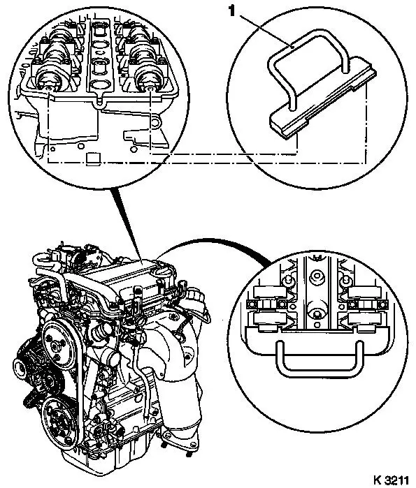
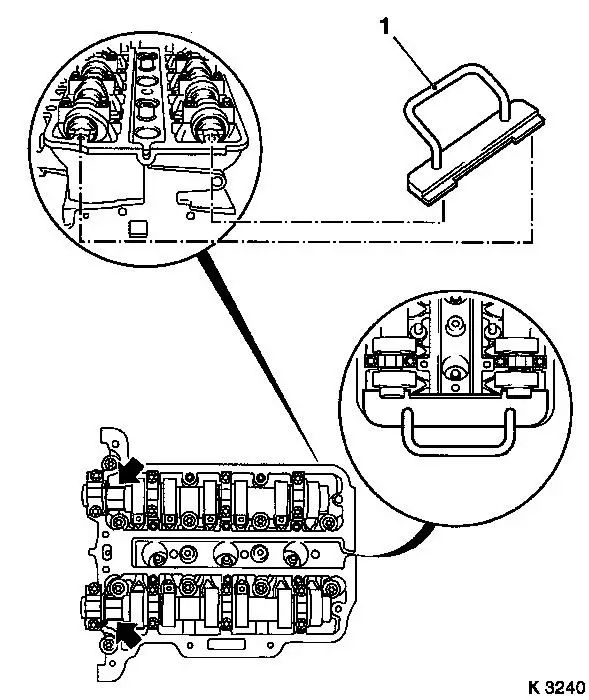
| 45. |
Insert KM-953 (1)
Note: KM-953 must engage in camshaft groove
|
|
| 47. |
Lock chain tensioner
| • |
Remove closure bolt (1)
|
| • |
Load intake camshaft in direction of arrow via hexagonal
section using an open-ended spanner
|
|
|
|
|
| 48. |
Remove sliding rail (1)
|
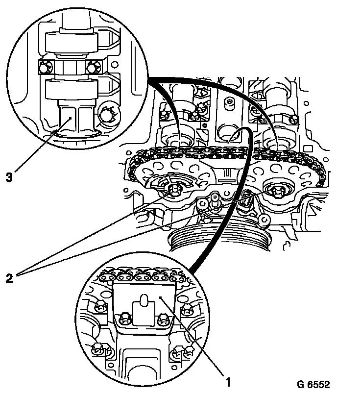
| 49. |
Detach camshaft sprockets
| • |
Unscrew 2 bolts (2)
| – |
Counterhold camshafts at hexagonal section (3)
|
|
| • |
Remove phase sensor disc
|
|
|
| 50. |
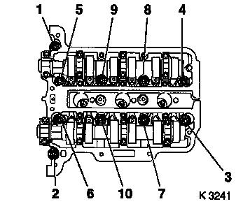
Remove cylinder head bolts
Note: Undo bolts in
order shown
|
| 51. |
Remove cylinder head
Note: Second person
required
| • |
Guide chain tensioner past tensioning rail
|
| • |
Place cylinder head on wooden blocks
|
| • |
Remove cylinder head gasket
|
|
|
|
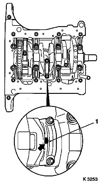
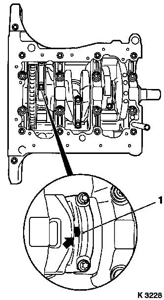
| 54. |
Remove con-rod bearing caps for no.2 cylinder (1)
Note: The mating
surfaces of the cod-rods and con-rod bearing caps form an
individual fit and must not be damaged or interchanged. Do not lay
on mating surfaces.
| • |
Mark con-rods with con-rod bearing caps
|
| • |
Push piston with con-rod upwards
|
|
| 57. |
Turn crankshaft
| • |
Pull timing chain upwards
|
| • |
Set cylinder no.3 piston to BDC
|
|
|
|
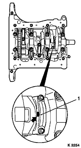
| 59. |
Remove con-rod bearing caps for no.3 cylinder (1)
Note: The mating
surfaces of the cod-rods and con-rod bearing caps form an
individual fit and must not be damaged or interchanged. Do not lay
on mating surfaces.
| • |
Mark con-rods with con-rod bearing caps
|
| • |
Push piston with con-rod upwards
|
|
| 63. |
Turn crankshaft
| • |
Pull timing chain upwards
|
| • |
Set cylinder no.1 piston to BDC
|
|
|
|
| 65. |
Remove con-rod bearing caps for no.1 cylinder (1)
Note: The mating
surfaces of the cod-rods and con-rod bearing caps form an
individual fit and must not be damaged or interchanged. Do not lay
on mating surfaces.
| • |
Mark con-rods with con-rod bearing caps
|
| • |
Push piston with con-rod upwards
|
|
| 68. |
Remove con-rod bearing shells
| • |
Mark con-rod bearing shells
Note: Observe order
|
|
|
|
 Install
| 69. |
Inspect components
Note: If cylinder head
is to be checked and overhauled : Remove all outer attaching parts
from cylinder head
|
| 70. |
Insert con-rod bearing shells
| • |
In con-rod, con-rod bearing cap
|
|
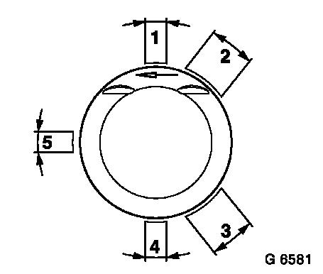
| 71. |
Adjust piston ring gaps
| • |
Turn piston rings
| – |
Upper rings in position (1)
|
| – |
Middle rings in position (4)
|
|
| • |
Turn oil scraper ring
| – |
Intermediate ring in position (5)
|
| – |
Steel band rings in position (2) or (3)
|
|
|
|
|
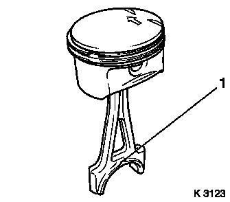
| 72. |
Install piston for no.1 cylinder
Note: Arrow on bottom
of piston points to engine timing side. Bead (1) on con-rod should
face transmission side
| • |
Coat piston and cylinder bore with engine oil
|
| • |
Compress piston rings with piston ring tensioner
|
|
|
|
| 74. |
Attach con-rod bearing cap
Note: Bead on con-rod
bearing cap should face transmission side
| • |
Coat con-rod journal with engine oil
|
| • |
Tighten 2x bolts 10 Nm + 60° +
15° (M6)
| – |
From engine number 19P13554 13 Nm +
60° + 15° (M6.5)
|
|
|
| 76. |
Turn crankshaft
| • |
Pull timing chain upwards
|
| • |
Set con-rod bearing journal to BDC
|
|
| 77. |
Install piston for no.3 cylinder
Note: Arrow on bottom
of piston points to engine timing side. Bead (1) on con-rod should
face transmission side
| • |
Coat piston and cylinder bore with engine oil
|
| • |
Compress piston rings with piston ring tensioner
|
|
| 79. |
Attach con-rod bearing cap
Note: Bead on con-rod
bearing cap should face transmission side
| • |
Coat con-rod journal with engine oil
|
| • |
Tighten 2x bolts 10 Nm + 60° +
15° (M6)
| – |
From engine number 19P13554 13 Nm +
60° + 15° (M6.5)
|
|
|
| 81. |
Turn crankshaft
| • |
Pull timing chain upwards
|
| • |
Set con-rod bearing journal to BDC
|
|
| 82. |
Install piston for no.2 cylinder
Note: Arrow on bottom
of piston points to engine timing side. Bead (1) on con-rod should
face transmission side
| • |
Coat piston and cylinder bore with engine oil
|
| • |
Compress piston rings with piston ring tensioner
|
|
| 84. |
Attach con-rod bearing cap
Note: Bead on con-rod
bearing cap should face transmission side
| • |
Coat con-rod journal with engine oil
|
| • |
Tighten 2x bolts 10 Nm + 60° +
15° (M6)
| – |
From engine number 19P13554 13 Nm +
60° + 15° (M6.5)
|
|
|
| 86. |
Lock crankshaft
Note: Second person
required
| • |
Pull timing chain upwards
|
| • |
Turn crankshaft uniformly until KM-952 engages
|
|
|
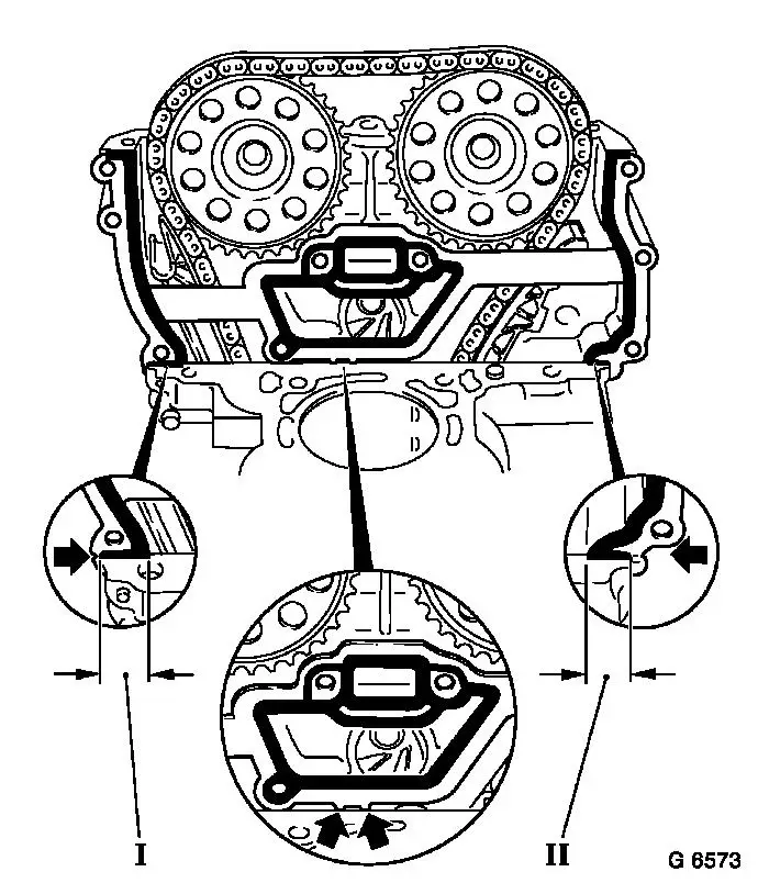
| 87. |
Remove timing case gasket
| • |
Cut through elastomer sealing lips (dimension I and II) from
inside outwards flush to cylinder block
|
| • |
Carefully bend gasket at designated break points (arrows)
|
|
| 88. |
Clean sealing surfaces
| • |
Cylinder block, cylinder head, timing case, exhaust manifold,
oil filter housing, thermostat housing, cylinder head cover
|
|
|
| 89. |
Inspect components
Note: If cylinder head
is to be checked and overhauled : Remove all outer attaching parts
from cylinder head
| • |
Cylinder block, cylinder head, timing case, exhaust manifold,
oil filter housing, thermostat housing, cylinder head cover
|
|
| 90. |
Check for plane surface
| • |
Cylinder head, cylinder block
|
| • |
With straightedge, feeler gauge
|
|
|
|
|
| 91. |
Replace cylinder head gasket
| • |
Cut off protruding elastomer (dimension I) on timing case
side
|
|
|
|
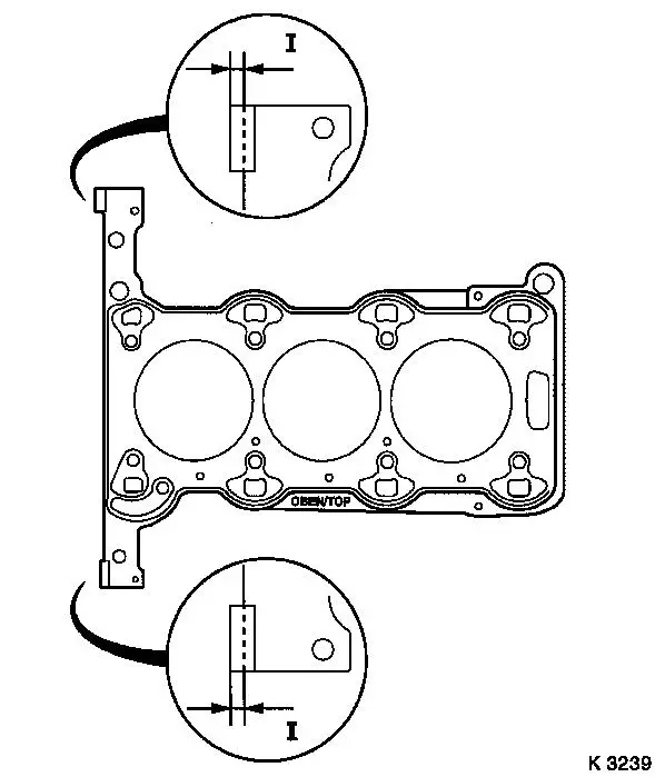
| 92. |
Apply sealant (dimension I = 2 mm)
Note: Complete assembly
operations within 10 minutes
| • |
Attach cylinder head gasket
| – |
OBEN/TOP mark must point upwards.
|
|
|
|
|
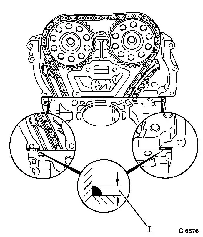
| 93. |
Fit timing case upper gasket (1)
| • |
Apply sealant (dimension I = 2 mm)
|
| • |
Insert 2x upper fastening bolts into timing case (arrows)
Note: Fastening screws
are used to fix the upper timing case gasket in position
|
| • |
Attach gasket
Note: Push on in
vicinity of sealant
|
|
|
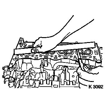
| 94. |
Attach cylinder head
Note: Second person
required
| • |
Guide KM-955-1 through aperture in
timing case
|
| • |
Guide chain tensioner past tensioning rail
|
| • |
Insert pin in guide rail
|
|
| 95. |
Fasten cylinder head
| • |
Replace cylinder head bolts
| – |
Screw in bolts by several threads
|
|
| • |
Attach timing case.
| – |
Tighten 3x bolts (1) 8 Nm
|
|
| • |
Position cylinder head by tapping with rubber mallet in
direction of timing case
|
| • |
Tighten 10x cylinder head bolts 25 Nm +
60° + 60° + 60°
| – |
Note tightening sequence.
|
|
|
|
|
| 96. |
Install timing case fastening bolts
- Undo lower 3 bolts of cylinder head again (previously installed
bolts)
- Coolant pump
- Tighten 4x bolts (1) 8 Nm
- Timing case
- Tighten 5x bolts (arrows) 8
Nm
|
|
|
|
| 97. |
Adjust camshafts
| • |
Insert KM-953 (1)
| – |
"Turn" the camshafts at hexagonal section (arrows)
|
|
|
|
| 98. |
Attach camshaft sprockets
| • |
Attach intake camshaft sprocket with phase sensor disc (2)
| – |
Bolt in bolt
Note: It must be
possible to rotate phase sensor disk by hand
|
|
| • |
Attach exhaust camshaft sprocket
|
|
| 100. |
Remove KM-955-1
| • |
Tighten chain tensioner closure bolt 50
Nm
|
|
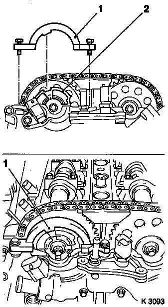
| 101. |
Attach KM-954
| • |
Rotate phase sensor disk until KM-954
(1) can be attached to timing case
|
|
|
|
| 102. |
Fasten camshaft sprockets
Note: Tightening torque
of 10 Nm is used to secure the
camshaft sprockets and the phase sensor disk
| • |
Tighten 2x bolts (2) 10 Nm
Note: First tighten
intake camshaft sprocket bolt
| – |
Counterhold camshafts at hexagonal section (1)
|
|
|
| 103. |
Remove retaining tools
Note: Retaining tools
must not be used for counterholding
| • |
KM-952 , KM-953 , KM-954
|
|
| 104. |
Fasten camshaft sprockets
Note: Second person
required
| • |
Tighten 2 bolts (2) 50 Nm +
60°
Note: First tighten
intake camshaft sprocket bolt
| – |
Counterhold camshafts at hexagonal section
|
|
|
|
|
| 106. |
Remove retaining tools
| • |
KM-952 , KM-953 , KM-954
|
|
| 107. |
Attach cylinder head cover (1)
| • |
Renew gasket (2) and seal rings
|
| • |
Apply sealant (dimension I = 2 mm)
Note: Complete assembly
operations within 10 minutes
|
| • |
Attach engine vent hose
|
|
|
|
| 108. |
Attach ignition module
|
| 109. |
Install oil filter housing
| • |
Attach oil filter housing cover
|
|
| 110. |
Install coolant connection
|
| 111. |
Install exhaust manifold
|
| 112. |
Attach exhaust manifold heat shield
|
| 113. |
Attach left engine transport shackle
|
| 114. |
Install oil dipstick guide tube
|
| 115. |
Install oxygen sensor, mixture regulation, heated
| • |
Apply assembly paste (white) to thread
|
| • |
Tighten oxygen sensor 40 Nm
|
| • |
Connect wiring harness plug
|
|
| 116. |
Install upper radiator hose
|
| 117. |
Attach coolant pump ribbed V-belt pulley
|
| 118. |
Install ribbed V-belt
Note: Note running
direction
| • |
Tension ribbed V-belt tensioner with KM-6131
|
| • |
Release ribbed V-belt tensioner
|
|
| 119. |
Fasten coolant pump ribbed V-belt pulley
|
| 120. |
Install right engine bracket
| • |
Tighten 2x upper bolts 60 Nm
|
| • |
Fasten engine damping block
|
|
| 122. |
Fasten right engine bracket
| • |
Tighten lower bolt 60 Nm
|
|
| 126. |
Attach oil baffle plate
|
| 127. |
Attach oil pan
Note: Note tightening
sequence.
| • |
Tighten 14x bolts at crankshaft bearing bridge 10 Nm
|
| • |
Tighten 3x bolts at transmission 40
Nm
|
|
| 128. |
Attach closure bolt of crankshaft bearing bridge
|
| 129. |
Attach engine management wiring harness
| • |
Attach wiring harness for starter
|
|
| 130. |
Attach exhaust system
| • |
Connect oxygen sensor (catalytic converter control) wiring
harness plug.
|
|
| 131. |
Install ribbed V-belt cover
Note: With "ECO" model
variant - install lower engine compartment cover
|
| 133. |
Install engine management wiring harness
| • |
Connect wiring harness for engine management
| – |
Connect 12x wiring harness plugs
|
| – |
Attach 3x ground cables
|
|
| • |
On Z 10 XEP: Fit fuel rail cover
|
|
| 134. |
Attach brake servo vacuum line
| • |
Connection must audibly engage
|
|
| 135. |
Attach fuel evaporation hose
|
| 136. |
Attach fuel line
| • |
Attach fuel line
| – |
Connection must audibly engage
|
|
|
| 137. |
Attach heater return hose
|
| 138. |
Fit heater supply hose to coolant pump
|
| 139. |
Fit 2x throttle body preheater hoses
| • |
To throttle valve pipe, coolant pump
|
|
| 141. |
Install air cleaner housing
| • |
On Z 10 XEP: Fit air intake hose
|
| • |
Attach engine vent hose
|
| • |
Clip in tank vent valve
|
| • |
Connect 2 wiring harness plugs
|
|
| 142. |
Close coolant drain bolt
|
| 143. |
Top up and bleed cooling system – see operation "Cooling
System, Top up and Bleed"
|
| 144. |
Top up engine oil
| • |
Observe specified engine oil quantity
|
| • |
Start engine and allow to run until oil pressure telltale
extinguishes.
|
| • |
Check engine oil level; correct if necessary
|
|
| 146. |
Program volatile memory
|
|
