|
Engine Using A Short Block, Repair (Z 18 XE,
without Air Conditioning, LHD)
Note: The customer
should be informed of the choice between ECOService and
ECOService-Flex before the oil change.
 Remove Remove
| 2. |
Detach manual transmission from engine 
|
| 3. |
Drain engine oil
| • |
Place collecting basin underneath.
|
|
| 4. |
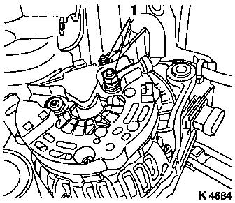
Detach alternator
| • |
Detach alternator shackle
|
| • |
Disconnect alternator wiring harness
|
|
|
|
| 5. |
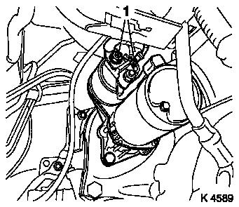
Remove wiring harness for starter
|
|
|
| 6. |
Detach engine vent hose from cylinder head cover
|
| 7. |
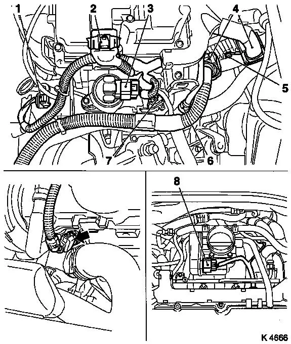
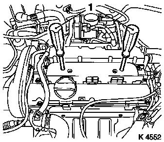
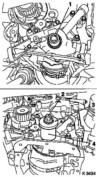
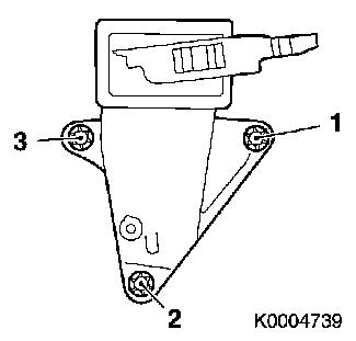
Remove wiring harness for engine management
| • |
Disconnect 11x wiring harness plugs
| – |
Throttle valve module (8), engine control unit (4), knock
sensor (6), combination plug (7), EGR valve (3), ignition module
(2), coolant temperature sensor (arrow), camshaft sensor, mixture
regulation heated oxygen sensor (1), crankshaft sensor
|
|
| • |
Detach ground cable (5)
|
| • |
Remove wiring trough
| – |
Unscrew from engine transport shackle
|
|
|
|
|
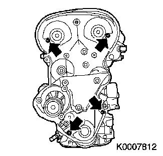
| 8. |
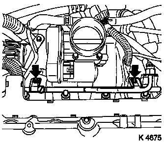
Remove fuel distributor pipe
| • |
Unscrew 2 bolts (arrows)
|
| • |
Pull out fuel distributor pipe with injectors and engine
management wiring harness
|
|
|
|
| 9. |
Remove upper part of toothed belt cover
| • |
Unclip from rear toothed belt cover
|
|
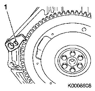
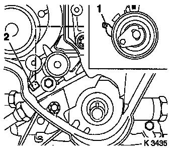
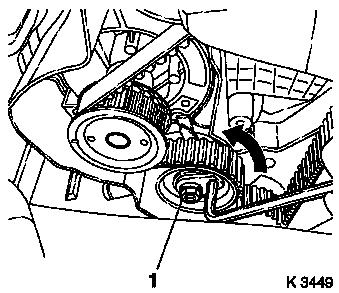
| 10. |
Detach crankshaft ribbed V-belt pulley
| • |
Block flywheel using KM-652 (1)
|
|
|
|
| 11. |
Remove camshaft sensor (1)
|
|
|
| 12. |
Detach lower part of toothed belt cover
| • |
Unclip from rear toothed belt cover
|
|
|
|
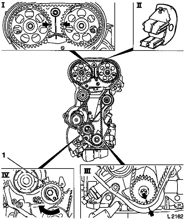
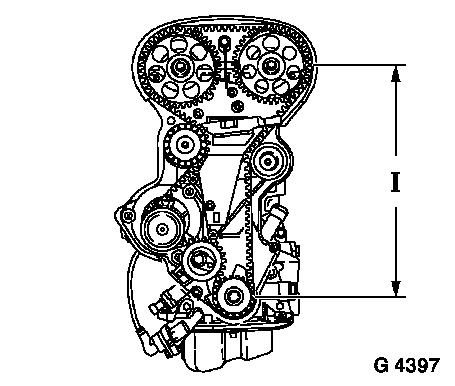
| 13. |
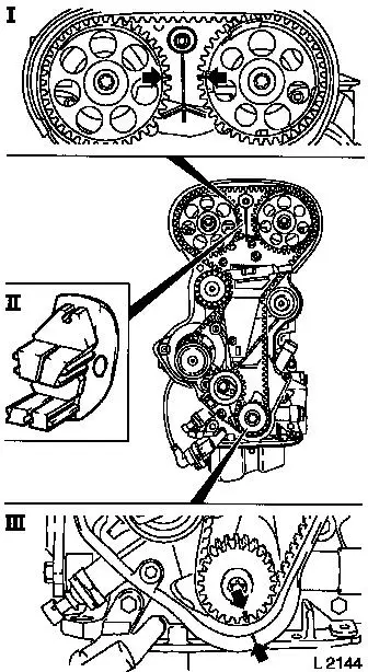
Set 1st cylinder to TDC of combustion stroke
| • |
Set crankshaft to mark.
| – |
Turn crankshaft evenly
Note: Marks on
crankshaft ribbed V-belt pulley and rear toothed belt cover must
align (III).
|
|
| • |
Fix camshaft sprockets in position.
Note: Marks must be
opposite one another and aligned with the top edge of the cylinder
head (I)
|
|
| 14. |
Remove toothed belt
| • |
Release toothed belt tension roller (IV)
Note: Mark running
direction.
| – |
Turn adjusting eccentric in direction of arrow (clockwise)
until pointer (1) of the toothed belt tension roller is located
just before left stop.
|
|
|
|
|
| 15. |
Remove ignition module
Important: Do not tilt
|
| • |
Extract using KM-6009 (1)
|
|
|
|
| 16. |
Detach preheater line for throttle valve module
|
| 17. |
Detach cylinder head cover
|
|
|
| 18. |
Remove camshaft sprockets
| • |
Unscrew 2 bolts
| – |
Counterhold camshafts at hexagonal section
|
|
|
|
|
| 19. |
Remove intake side toothed belt guide roller
|
| 20. |
Remove exhaust side toothed belt guide roller
|
| 21. |
Remove right engine bracket (3)
|
| 22. |
Remove toothed belt tension roller
|
|
|
| 23. |
Remove toothed belt drive pulley
| • |
Unscrew crankshaft ribbed V-belt pulley bolt
|
| • |
Remove toothed belt drive pulley
|
|
| 24. |
Remove rear toothed belt cover
| • |
Unscrew 4 bolts (arrows)
|
|
|
|
| 27. |
Remove oil dipstick guide tube
|
| 28. |
Install oil drain bolt
|
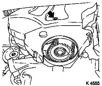
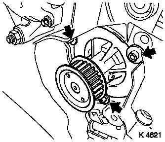
| 29. |
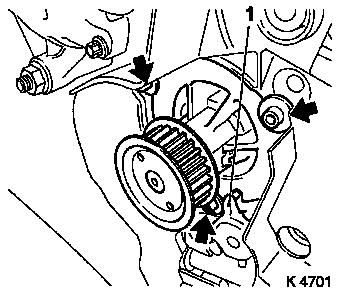
Remove coolant pump
| • |
Place another collecting basin underneath
|
| • |
Unscrew 3 bolts (arrows)
|
|
|
|
| 30. |
Detach coolant pipe
| • |
Remove coolant pipe and hose
|
| • |
Unclip heating hose from bracket
|
|
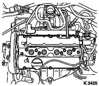
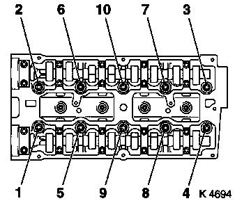
| 31. |
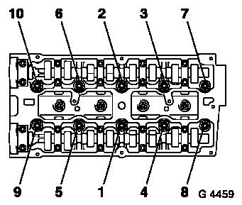
Remove cylinder head bolts
| • |
Unscrew 10 bolts
Note: Undo bolts in
order shown.
| – |
Loosen 10x bolts (180 °)
|
|
|
|
|
Important: Place cylinder head on
wooden blocks.
|
| 32. |
Remove cylinder head
Note: Second person
required
| • |
Remove cylinder head gasket
|
|
| 35. |
Remove oil filter housing cover
| • |
Place another collecting basin underneath
|
|
| 36. |
Detach oil filter housing
|
| 37. |
Remove crankshaft sensor
|
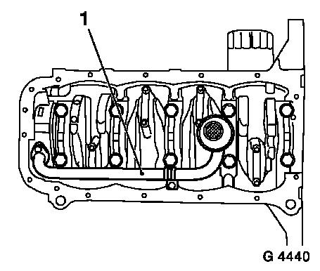
| 39. |
Remove oil intake pipe (1)
|
|
|
| 41. |
Remove cylinder block
| • |
Suspend engine on workshop crane
|
|
 Install
| 42. |
Install cylinder block
| • |
Attach KM-412-3 to engine
|
|
| 44. |
Drive 6x guide sleeves into cylinder block with KM-427
|
| 45. |
Clean sealing surfaces
| • |
Cylinder head, cylinder head cover, oil pan, oil pump,
crankshaft rear bearing cap, coolant pump, oil filter housing
|
|
| 46. |
Inspect components
| • |
Cylinder head, cylinder head cover, oil pan, oil intake pipe,
oil pump, ribbed V-belt, ribbed V-belt tensioner, ribbed V-belt
pulleys, toothed belt drive, coolant pump, oil filter housing
|
|
| 47. |
Recut 5x threads in oil pump
|
| 48. |
Remove crankshaft front seal ring
Important: Do not damage sealing
surface.
|
| • |
Lever out seal ring
|
|
| 49. |
Install oil pump
| • |
Replace gasket
Note: Insert bolts with
locking compound
|
|
| 50. |
Install crankshaft front seal ring
| • |
Coat seal lip with grease
|
| • |
Attach KM-6010 to crankshaft journal
(1)
|
| • |
Slide seal ring over KM-6010
|
| • |
Install crankshaft front seal ring
| – |
With KM-6010 (4), bolt (2) and
crankshaft ribbed V-belt pulley washer (3)
|
|
|
|
|
| 51. |
Attach oil intake pipe
| • |
Replace seal ring
Note: Insert boots with
locking compound (red).
|
|
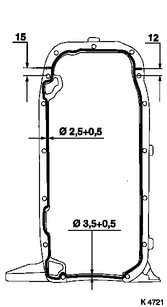
| 52. |
Attach oil pan
Important: Complete installation
work within 10 minutes
|
| • |
Apply sealant
|
| • |
At cylinder block
| – |
Tighten 12x bolts 10 Nm
|
|
|
|
|
| 53. |
Install crankshaft sensor
|
| 54. |
Attach oil filter housing
|
| 55. |
Attach oil filter housing cover
|
| 57. |
Install knock sensor
Important: Correct tightening
torque must be used.
|
| • |
Tighten bolt 20 Nm
|
|
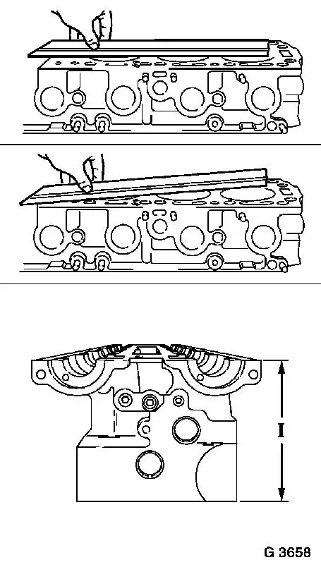
| 58. |
Check for plane surface
Important: Cylinder head must not
be resurfaced.
|
| • |
With straightedge, feeler gauge
|
| • |
Measure cylinder head height
| – |
Sealing surface to sealing surface 135.85 - 136.00 (dimension
I)
|
|
|
|
|
| 59. |
Replace cylinder head gasket
| • |
Attach cylinder head gasket
Note: OBEN/TOP mark
must face upwards.
|
|
| 60. |
Attach cylinder head
Note: Second person
required
|
| 61. |
Fasten cylinder head
| • |
Replace cylinder head bolts
|
| • |
Tighten 10 cylinder head bolts 25 Nm +
90°+ 90°+ 90° + 45°
Note: Note tightening
sequence.
|
|
|
|
| 63. |
Install coolant pump
| • |
Coat sealing surface with silicon grease
|
| • |
Replace seal ring
Note: Ensure that the
lug of the oil pump (1) engages in the groove of the coolant
pump
|
| • |
Tighten 3x bolts (arrows) 8 Nm
|
|
|
|
| 64. |
Attach flywheel
| • |
Tighten 6x bolts 35 Nm + 30° +
15°
|
|
| 66. |
Attach rear toothed belt cover
|
| 67. |
Install toothed belt drive gear
| • |
Install crankshaft V-belt pulley bolt
|
|
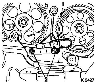
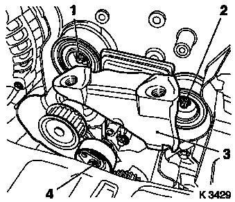
| 68. |
Install toothed belt tension roller
Important: Detent lever (1) of
toothed belt tension roller must engage in guide web (2) of oil
pump.
|
| • |
Bolt in bolt
Note: Adjust toothed
belt tension before tightening bolt.
|
|
|
|
| 69. |
Attach right engine bracket
| • |
Tighten 3x bolts 65 Nm + 45° +
15°
|
| • |
Note tightening sequence.
|
|
|
|
| 70. |
Install intake side toothed belt guide roller
Important: The toothed belt guide
roller with the greater diameter is installed at the intake
side.
|
| • |
Tighten bolt 25 Nm
|
|
| 71. |
Install exhaust side toothed belt guide roller
|
| 72. |
Install camshaft sprockets
Note: Attach camshaft
sprocket with cylinder recognition to exhaust camshaft.
|
| 73. |
Fasten camshaft sprockets
Note: Second person
required
| • |
Tighten 2x bolts 50 Nm + 60° +
15°
| – |
Counterhold camshafts at hexagonal section
|
|
|
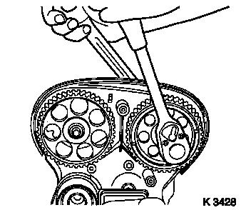
| 74. |
Fix camshaft sprockets in position.
Note: Marks must be
opposite one another and aligned with the top edge of the cylinder
head (I)
| • |
Use KM-852 (II)
| – |
Turn the camshafts at hexagonal section
|
|
|
| 75. |
Lock crankshaft
| • |
Set crankshaft to mark.
| – |
Turn crankshaft evenly
Note: Marks on drive
gear toothed belt and rear toothed belt cover must align (III).
|
|
|
|
|
| 76. |
Install toothed belt
Note: Pay attention to
direction of travel and timing marks.
| • |
Position toothed belt
Note: Tensioned side
must be taut (I).
|
|
|
|
| 77. |
Tension toothed belt
| • |
Tension toothed belt tension roller
| – |
Turn adjusting eccentric in direction of arrow (anticlockwise)
until pointer of the toothed belt tension roller is located just
before left stop
|
|
| • |
Fasten toothed belt tension roller bolt (1)
|
|
|
|
| 79. |
Timing, Check
| • |
Turn crankshaft (720°)
| – |
At crankshaft ribbed V-belt pulley bolt
Note: In direction of
engine rotation.
|
|
| • |
Set crankshaft to mark.
Note: Marks on drive
gear toothed belt and rear toothed belt cover must align (III).
|
| • |
Use KM-852 (II)
Note: Marks must be
opposite one another and aligned with the top edge of the cylinder
head (I)
|
|
|
|
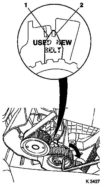
| 81. |
Adjust toothed belt tension
| • |
Release toothed belt tension roller
|
| • |
Turn adjustment eccentric in the direction of the arrow
(clockwise) until pointer (1) is aligned with the notch mark at the
toothed belt tension roller (2).
| – |
Adjust used toothed belts to the marking USED
|
| – |
Adjust new toothed belts to the marking NEW
|
|
| • |
Tighten toothed belt tension roller bolt 20 Nm
|
|
| 82. |
Check toothed belt tension
| • |
Turn crankshaft (720°)
Note: Pointer on the
toothed belt tension roller and notch mark must align.
| – |
Adjust used toothed belts to the marking USED
|
| – |
Adjust new toothed belts to the marking NEW
|
|
|
|
|
| 83. |
Recut 2x threads
| • |
Camshaft sensor to cylinder head
|
|
| 84. |
Install camshaft sensor
| • |
Insert bolts with locking compound (red)
|
|
| 85. |
Install lower part of toothed belt cover
| • |
Clip to rear of toothed belt cover
|
|
| 86. |
Install upper part of toothed belt cover
| • |
Clip to rear of toothed belt cover
|
|
| 87. |
Attach crankshaft ribbed V-belt pulley
| • |
Tighten bolt 95 Nm + 30°+
15°
|
|
| 88. |
Install oil dipstick guide tube
|
| 89. |
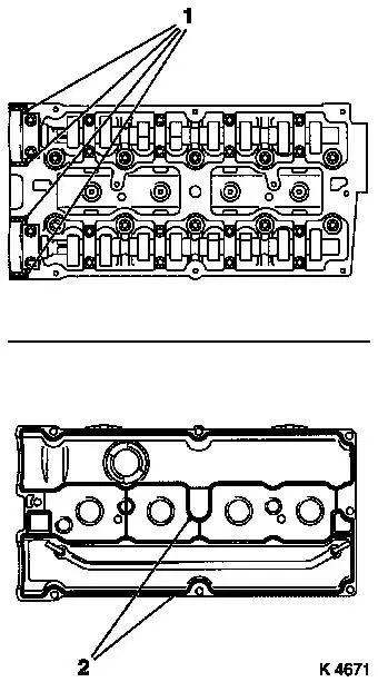
Attach cylinder head cover
Important: Complete installation
work within 10 minutes
|
| • |
Apply sealant (1)
|
|
|
|
| 90. |
Attach preheater line for throttle valve module
|
| 91. |
Attach ignition module
|
| 92. |
Install fuel distributor pipe
|
| 93. |
Attach wiring harness for engine management
| • |
Connect 8x wiring harness plugs
|
| • |
Clip on wiring harness.
|
|
| 94. |
Attach engine vent hose
|
| 95. |
Attach wiring harness for starter
| • |
Clip on wiring harness.
|
|
| 96. |
Attach alternator
| • |
Attach alternator wiring harness
|
| • |
Fasten alternator shackle
|
| • |
Tighten bolt, stud 20 Nm
|
| • |
Clip on wiring harness.
|
|
| 97. |
Top up engine oil
| • |
Observe specified engine oil quantity
|
|
| 98. |
Attach manual transmission to engine
|
| 100. |
Reset service interval using TECH 2
Note: If the customer
decides to have ECOService - connect TECH2 and reprogram engine
control unit
|
| 101. |
Fill out the service sticker
|
|
