|
Remove and install both camshafts (Z 12 XE, Z 12
XEP, Z 14 XEP, with air conditioning, LHD)
 Remove Remove
| 2. |
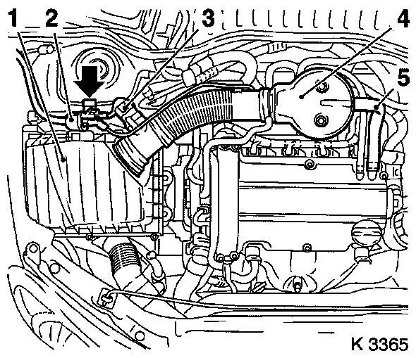
Remove air cleaner housing (1)
| • |
Disconnect 2 wiring harness plugs
| – |
Hot film mass air flow sensor (3), tank vent valve (2)
|
|
| • |
Remove suction pipe (4)
| – |
Detach engine vent hose (5)
|
|
| • |
For Z 12 XEP, Z 14 XEP: detach air intake hose
|
|
|
|
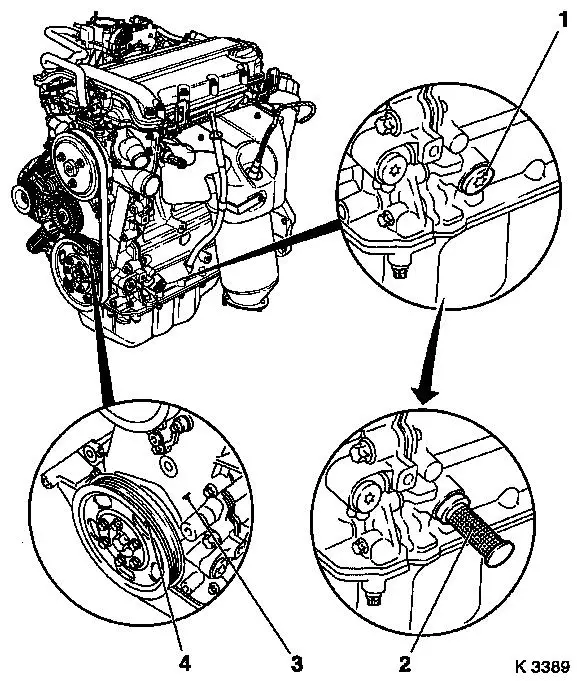
| 3. |
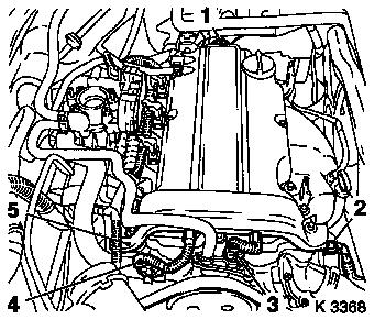
Disconnect 4 cable management wiring harness plugs
| • |
Oil pressure switch (2), coolant temperature sensor (3),
camshaft sensor (4) and ignition module (1)
|
| • |
Unclip wiring trough (5)
|
| • |
Set wiring harness to one side
|
|
|
|
| 4. |
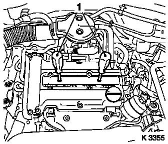
Remove ignition module
| • |
Remove ignition module cover
|
| • |
Extract using KM-6009 (1)
Note: Do not tilt
|
|
| 5. |
Remove cylinder head cover
| • |
Detach 2 engine vent hoses
|
|
|
|
| 7. |
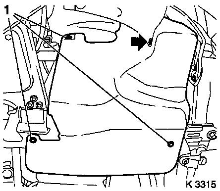
Remove ribbed V-belt cover
|
|
|
|
| 8. |
Unscrew crankshaft bearing bridge closure bolt (1)
|
| 9. |
Set no.1 cylinder to TDC
| • |
Turn crankshaft uniformly until KM-952 engages
| – |
Mark on crankshaft belt pulley (4) must line up with lug (3) on
timing case
|
|
|
|
|
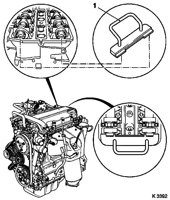
| 10. |
Insert KM-953
| • |
KM-953 must engage in camshaft
groove
|
|
|
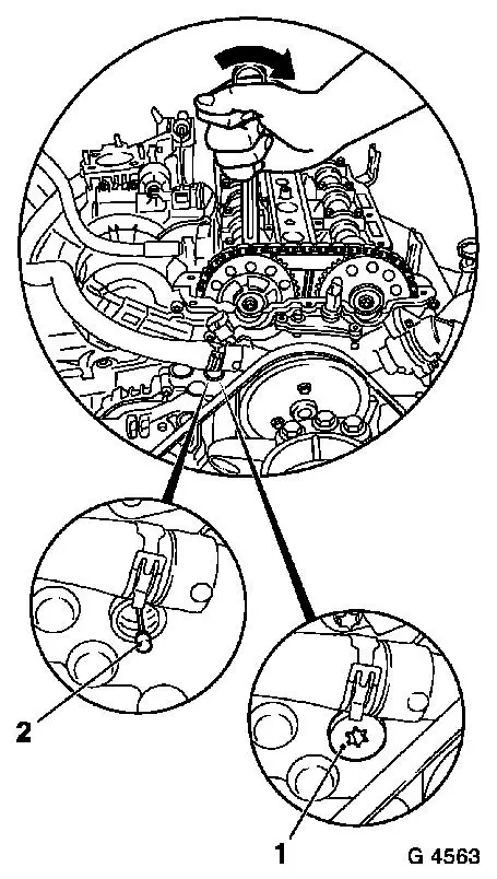
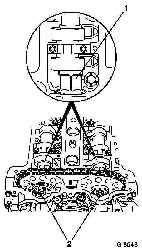
| 11. |
Lock chain tensioner
| • |
Unscrew closure bolt (1)
|
| • |
Load intake camshaft in direction of arrow via hexagonal
section using an open-ended spanner
|
|
|
|
|
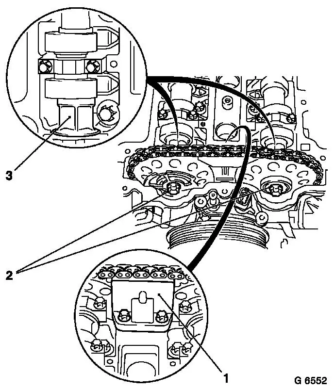
| 12. |
Remove sliding rail (1)
|
| 13. |
Detach camshaft sprockets
| • |
Unscrew 2 bolts (2)
| – |
Counterhold camshafts at hexagonal section (3)
|
|
| • |
Remove phase sensor disc
|
|
|
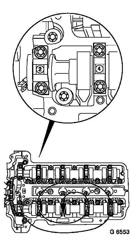
| 14. |
Remove exhaust camshaft
| • |
Remove camshaft bearing cap
|
| • |
Release camshaft bearing cap working in inward spiral from
outside in steps of 1/2 to 1 turn
| – |
Camshaft must be evenly released from the bearing seats
|
|
|
| 15. |
Remove intake camshaft
| • |
Remove camshaft bearing cap
|
| • |
Release camshaft bearing cap working in inward spiral from
outside in steps of 1/2 to 1 turn
| – |
Camshaft must be evenly released from the bearing seats
|
|
|
|
|
 Install
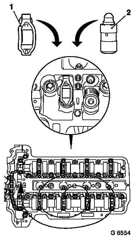
| 16. |
Inspect components
Note: If cylinder head
is to be checked and overhauled : Remove all outer attaching parts
from cylinder head.
| • |
Camshafts, cylinder head
|
|
| 17. |
Install intake camshaft
| • |
Coat sliding surfaces with MoS2 lubricating paste
|
| • |
Insert camshaft, camshaft bearing cap
| – |
Observe installation position and allocations
|
|
| • |
Install camshaft bearing cap
| – |
Tighten 8 camshaft bearing cap bolts 8
Nm
Note: Tighten in stages
in a spiral from inside to outside
|
|
|
| 18. |
Install exhaust camshaft
| • |
Coat sliding surfaces with MoS2 lubricating paste
|
| • |
Insert camshaft, camshaft bearing cap
| – |
Observe installation position and allocations
|
|
| • |
Install camshaft bearing cap
| – |
Tighten 8 camshaft bearing cap bolts 8
Nm
Note: Tighten in stages
in a spiral from inside to outside
|
|
|
|
|
|
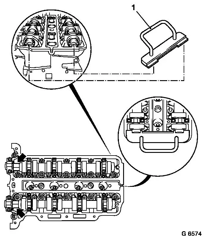
| 19. |
Adjust camshafts
| • |
Insert KM-953 (1)
| – |
"Turn" the camshafts at hexagonal section (arrows)
|
|
|
|
| 20. |
Attach camshaft sprockets
| • |
Attach intake camshaft sprocket with phase sensor disc (2)
| – |
Bolt in bolt
Note: It must be
possible to rotate phase sensor disk by hand
|
|
| • |
Attach exhaust camshaft sprocket
|
|
| 22. |
Remove KM-955-1
| • |
Tighten chain tensioner closure bolt 50
Nm
|
|
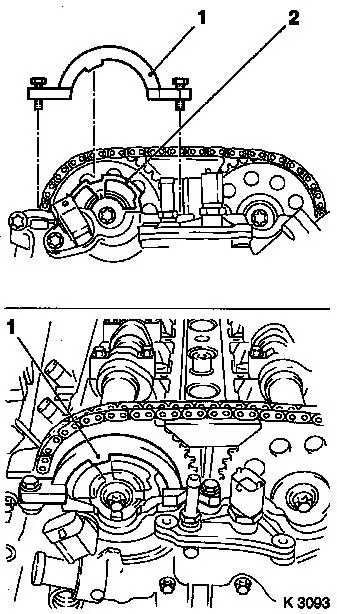
| 23. |
Attach KM-954
| • |
Rotate phase sensor disk (2) until KM-954 (1) can be attached to timing case
|
|
|
|
| 24. |
Fasten camshaft sprockets
Note: Tightening torque
of 10 Nm is used to secure the
camshaft sprockets and the phase sensor disk
| • |
Tighten 2 bolts (2) 10 Nm
Note: First tighten
intake camshaft sprocket bolt
| – |
Counterhold camshafts at hexagonal section (1)
|
|
|
| 25. |
Remove retaining tools
| • |
KM-952 , KM-953 , KM-954
Note: Retaining tools
must not be used for counterholding
|
|
| 26. |
Fasten camshaft sprockets
Note: Second person
required
| • |
Tighten 2 bolts 50 Nm + 60°
Note: First tighten
intake camshaft sprocket bolt
| – |
Counterhold camshafts at hexagonal section
|
|
|
|
|
| 28. |
Remove retaining tools
| • |
KM-952 , KM-953 , KM-954
|
|
| 29. |
Attach closure bolt of crankshaft bearing bridge
|
| 30. |
Install ribbed V-belt cover
|
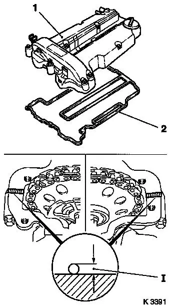
| 32. |
Attach cylinder head cover (1)
| • |
Renew gasket (2) and seal rings
|
| • |
Apply sealant (dimension I = 2 mm)
Note: Complete assembly
operations within 10 minutes
|
|
| 33. |
Attach 2 engine vent hoses
|
| 34. |
Attach ignition module
| • |
Attach ignition module cover
|
|
| 35. |
Install engine management wiring harness
| • |
Connect 4 wiring harness plugs
|
|
|
|
| 36. |
Install air cleaner housing
| • |
For Z 12 XEP, Z 14 XEP: attach air intake hose
|
| • |
Attach engine vent hose
|
| • |
Clip in tank vent valve
|
| • |
Connect 2 wiring harness plugs
|
|
|
