|
Valve seat, cut (in cylinder head)
Special service tools required:
Valve seat cutter set KM-340-G, KM-340-100
Note: For use of
valve cutter set KM-340-G / 340-100, consult the accompanying
instructions.
The guide drift is identical for the intake and exhaust
sides.
|
Valve stem Ø
|
Guide drift
|
|
5 mm
|
KM-340-30, KM-340-100-3
|
|
6 mm
|
KM-340-27, KM-340-100-4
|
|
7 mm
|
KM-340-7
|
|
8 mm
|
KM-340-23
|
|
Angle
|
Cutter
|
| |
for petrol engines
|
|
15°
|
KM-340-26, -28
|
|
30°
|
KM-340-11, -12, -13, -29, KM-340-100-1
|
|
45°
|
KM-340-11, -12, -13, -29, KM-340-100-2
|
|
60 °
|
KM-340-26, -28
|
| |
for diesel engines
|
|
15°
|
KM-340-25
|
|
45°
|
KM-340-25, KM-340-100-2
|
|
75°
|
KM-340-14
|
Caution
The 15° and 75° cutters must only be used for certain
diesel engines.
|
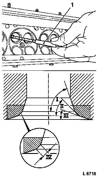
 Install
Insert guide drift (1) from valve cutter set in the valve guide
and tension. Ensure that the guide drift is inserted to 2 – 3
mm from the stop only. Ensure that the valve guides are OK. These
are used to hold the guide drift.
Procedure
|
Sequence of operations:
|
|
I
|
Lower correction angle
|
|
II
|
Valve seat angle
|
|
III
|
Upper correction angle
|
|
IV
|
Valve seat width
|
|
|
|
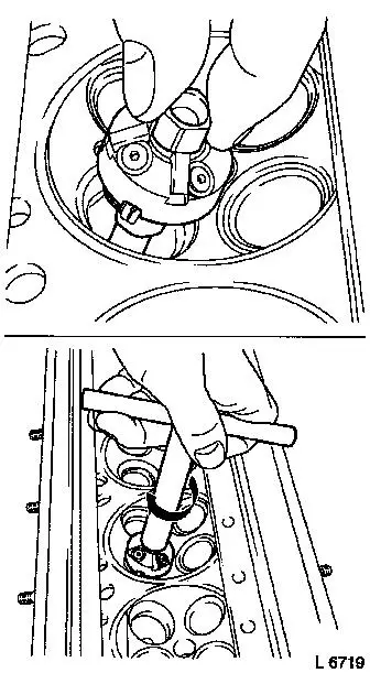
Slide the cutter over the guide drift at the specified angle.
Install turning knob.
Note: If necessary
release the cutting stones of the valve seat cutter and adjust them
to the diameter of the valve seat by sliding them.
Procedure
Cut valve seats and correction angle clockwise exerting light
pressure.
|
|
|
Release guide drift (1) and remove from
valve guide. The valve seat contact pattern is checked using a new
valve and blue ink.
- Lower correction angle
- Valve seat angle
- Upper correction angle
- Valve seat width
The valve width dimensions can be found in the "Technical
Data".
After cutting the valve seat, the valve indentation/installation
height of valves must be checked.
 Clean Clean
Clean cylinder head after completing operations.
The valves must be ground and ground-in before installation.
|
|
|
