|
J608200 Coolant Connection, Remove and Install (Z
18 XE, with Air Conditioning, LHD)
 Remove Remove
| 2. |
Disconnect battery
Note: In vehicles from
model year 04 onwards with ESP - the steering angle sensor loses
its basic adjustment each time the battery is disconnected and must
be recalibrated.
|
| 3. |
Remove engine cover.
| • |
Unscrew oil filler pipe cap
|
| • |
Screw on oil filler pipe cap
|
|
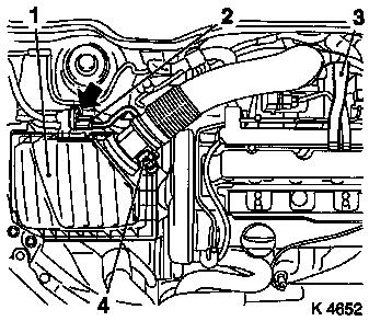
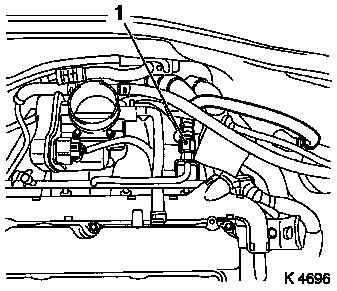
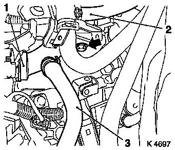
| 4. |
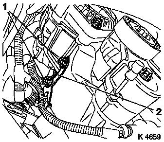
Remove air cleaner housing (1)
| • |
Disconnect wiring harness plug
| – |
Hot film mass air flow meter (4), tank vent valve (2)
|
|
| • |
Detach engine vent hose (3)
|
|
|
|
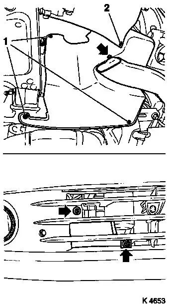
| 6. |
Remove right-hand air duct
| • |
Unscrew 3 bolts (arrows)
|
|
| 7. |
Remove ribbed V-belt cover
|
|
|
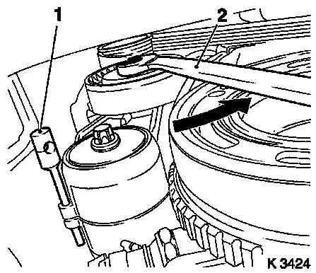
| 8. |
Remove ribbed V-belt
Note: Mark running
direction.
| • |
Tension ribbed V-belt tensioner in direction of arrow with
KM-913-A (2)
|
|
|
|
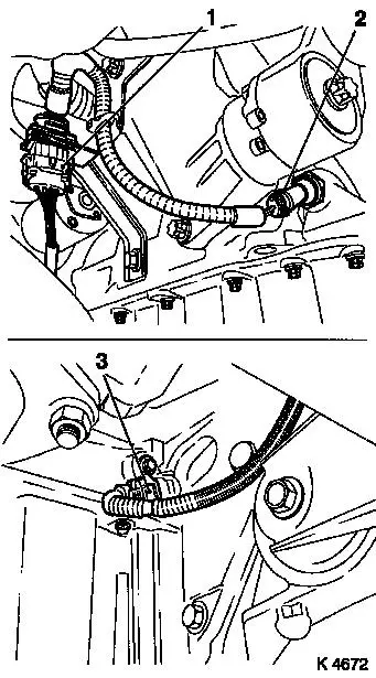
| 9. |
Remove wiring harness for engine management
| • |
Disconnect wiring harness plug
| – |
Catalytic converter control oxygen sensor (1), oil pressure
switch (2), crankshaft sensor (3)
|
|
|
|
|
| 10. |
Release alternator
| • |
Release alternator support
| – |
Unscrew 2 upper bolts (1)
|
|
|
|
|
| 11. |
Detach intake manifold support
|
|
|
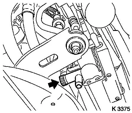
| 13. |
Drain coolant
| • |
Place collecting basin underneath.
|
| • |
Open drain bolt (arrow)
|
|
| 15. |
Disconnect camshaft sensor wiring harness plug
| • |
Disconnect wiring harness connector.
|
|
|
|
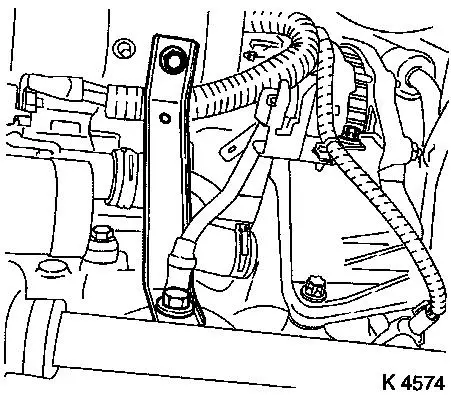
| 16. |
Remove alternator shackle
| • |
Remove ground cable (1)
|
| • |
Unscrew 2x bolts (4, 5)
|
| • |
Swing alternator backwards.
|
|
|
|
Important: Observe safety
precautions and national regulations
|
| 17. |
Release fuel pressure with KM-J-34730-91
| • |
Unscrew protective cap of test connection on fuel distributor
pipe
|
|
|

|
| 18. |
Detach fuel line (1) from fuel distributor pipe
|
| 19. |
Detach engine vent hose from cylinder head cover
|
| 20. |
Pull fuel evaporation hose from throttle valve module
|
|
|
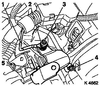
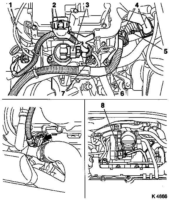
| 21. |
Remove wiring harness for engine management
| • |
Disconnect 9 wiring harness plugs
| – |
Throttle valve module (8), engine control unit (4), knock
sensor (6), combination plug (7), EGR valve (3), ignition module
(2), mixture regulation heated oxygen sensor (1), coolant
temperature sensor (arrow)
|
|
| • |
Detach ground cable (5)
|
| • |
Remove wiring trough
| – |
Unscrew from engine transport shackle
|
|
| • |
Set wiring harness to one side
|
|
|
|
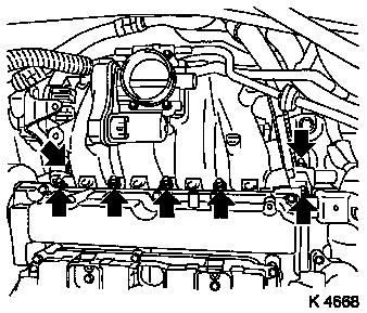
| 22. |
Remove fuel distributor pipe
| • |
Unscrew 2 bolts (arrows)
|
| • |
Pull out fuel distributor pipe with injectors and engine
management wiring harness
|
|
|
|
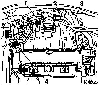
| 23. |
Release preheater line - throttle valve module (1)
| • |
Detach preheater hose from throttle valve module
|
| • |
Unscrew 2 bolts (arrows)
|
|
| 24. |
Detach preheater return hose for throttle valve module (2) from
throttle valve module
|
| 25. |
Detach heating return hose (3) from intake manifold
|
| 26. |
Remove right rear engine transport shackle (4)
|
|
|
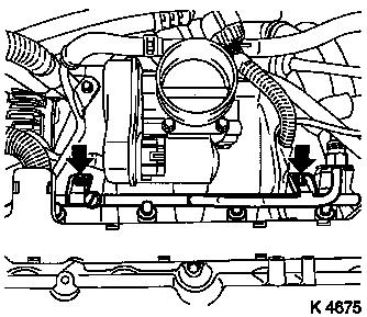
| 27. |
Remove intake manifold
| • |
Unscrew 7x nuts (arrows)
|
| • |
Remove brake servo vacuum line
|
|
|
|
| 28. |
Unclip knock sensor cable from coolant pipe
|
| 29. |
Detach heating supply hose (2) from coolant pipe
|
| 30. |
Detach coolant hose, coolant compensation tank (3) from coolant
pipe
|
| 31. |
Detach lower radiator hose (1) from coolant pipe
|
| 32. |
Remove coolant pipe
| • |
Detach from centre coolant hose
|
|
|
|
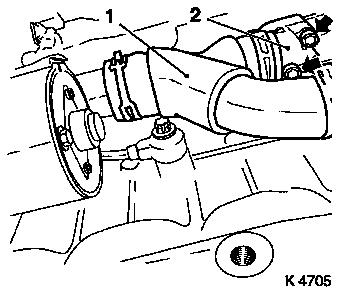
| 33. |
Remove centre coolant hose (1)
| • |
Detach coolant hose from coolant pump connection, coolant
flange
|
|
| 34. |
Remove coolant flange (2)
| • |
Unscrew 2x bolt (arrows)
|
|
|
|
 Install
| 35. |
Clean sealing surfaces
| • |
Intake manifold, cylinder head, coolant flange
|
|
| 36. |
Install coolant flange
|
| 37. |
Install centre coolant hose
|
| 39. |
Connect lower radiator hose
|
| 40. |
Attach coolant hose, coolant compensation tank
|
| 41. |
Attach heating supply hose
|
| 42. |
Clip on knock sensor cable
|
| 43. |
Install intake manifold
| • |
Attach brake servo vacuum line
| – |
Connection must audibly engage
|
|
|
| 44. |
Install right rear engine transport shackle
|
| 45. |
Attach heating return hose
|
| 46. |
Attach preheater return hose for throttle valve module
|
| 47. |
Fasten preheater line - throttle valve module
|
| 48. |
Install fuel distributor pipe
| • |
Replace 4x injector seal rings
|
| • |
Connect fuel distributor pipe with injectors and engine
management wiring harness
|
|
| 49. |
Attach wiring harness for engine management
| • |
Connect wiring harness plug
|
| • |
Attach ground cable with bracket for knock sensor wiring
harness plug
|
|
| 50. |
Attach fuel evaporation hose
|
| 51. |
Attach engine vent hose
|
| 53. |
Install alternator shackle
| • |
Tighten bolts, studs 20 Nm
|
|
| 54. |
Connect wiring harness plug from camshaft sensor
| • |
Connect wiring harness plug
|
|
| 56. |
Attach intake manifold support
|
| 57. |
Fasten alternator
| • |
Fasten alternator support
|
|
| 58. |
Attach wiring harness for engine management
| • |
Connect 3 wiring harness plugs
|
|
| 59. |
Install ribbed V-belt
Note: Observe running
direction and installation position
| • |
Slacken ribbed V-belt tensioner with KM-913-A
|
|
| 60. |
Close coolant drain bolt
|
| 61. |
Install ribbed V-belt cover
|
| 62. |
Install right-hand air duct
|
| 64. |
Install air cleaner housing
| • |
Attach engine vent hose
|
| • |
Clip in tank vent valve
|
| • |
Connect 2 wiring harness plugs
|
|
| 65. |
Install engine cover.
| • |
Unscrew oil filler pipe cap
|
| • |
Screw on oil filler pipe cap
|
|
| 67. |
Calibrate steering angle sensor
| • |
Rotate the steering wheel one time from its right-hand to its
left-hand stop
|
|
| 68. |
Program volatile memories
|
| 70. |
Program volatile memories
|
|
