|
Replacing accumulator
Important:
Cleanliness is of the utmost importance when working with the fuel
system. The smallest particle of dirt could cause engine
malfunction or contaminate the fuel system. Open fuel systems must
be sealed with a suitable plug from the Opel Parts catalogue (Cat.
no. 45 06 154 / Part no. 9201697). Plugs are intended for one-time
use only
 Remove Remove
| 2. |
Disconnect battery
| • |
Detach ground clamp from ground terminal
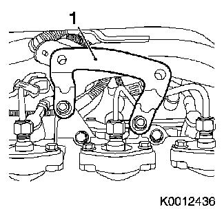
|
|
| 3. |
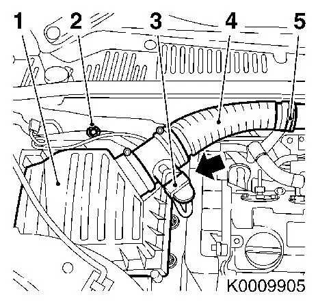
Remove air cleaner housing (1)
| • |
Disconnect wiring harness plug of hot film mass air flow meter
(3)
| – |
Release in direction of arrow
|
|
| • |
Remove air intake hose (4)
|
| • |
Disconnect wiring harness
|
|
|
|
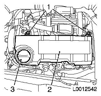
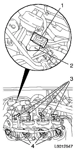
| 4. |
Remove engine cover (2)
| • |
Detach oil filler port cover (3)
|
| • |
Unclip engine cover from bracket
|
| • |
Attach oil filler port cover
|
|
|
|
| 5. |
Raise vehicle all the way
|
| 6. |
Drain coolant
| • |
Place collecting basin underneath.
|
|
| 7. |
Lower vehicle all the way
|
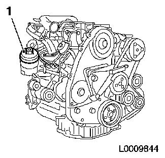
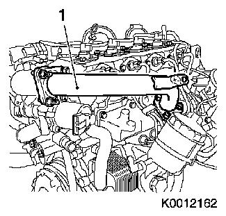
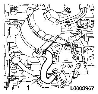
| 8. |
Unscrew oil filter housing cover (1) with oil filter
|
|
|
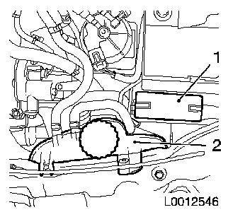
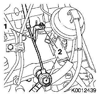
| 9. |
Detach fuse holder (1) from bracket
|
| 10. |
Remove coolant compensation tank (2)
| • |
Remove body-bound rivet
|
| • |
Unclip from upper front
|
|
|
|
|
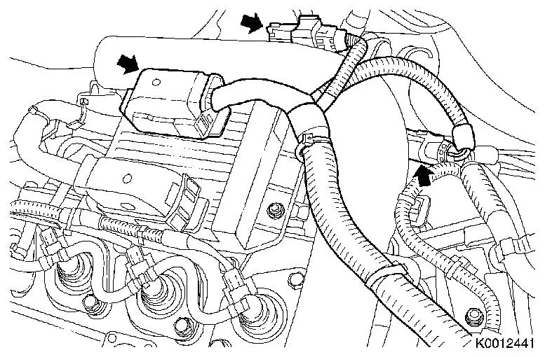
| 11. |
Remove engine management wiring harness
| • |
Disconnect 3 wiring harness plugs (arrows)
|
| • |
Detach ground cable from engine control unit
|
|
|
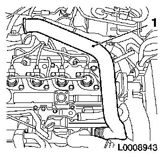
| 12. |
Remove air intake pipe
| • |
Detach from turbocharger
|
| • |
Detach engine vent hose from camshaft housing
|
|
|
|
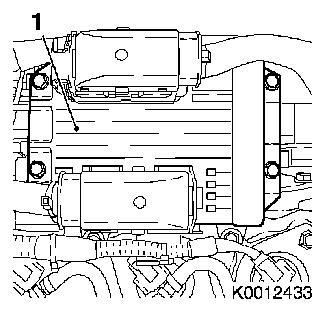
| 13. |
Remove engine control unit (1)
| • |
Disconnect wiring harness plug
|
|
|
|
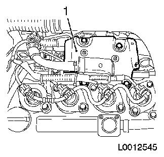
| 14. |
Remove engine control unit bracket (1)
|
|
|
| 15. |
Remove engine control unit bracket support (1)
|
|
|
| 16. |
Disconnect engine wiring harness
| • |
Disconnect 4 wiring harness plugs for injectors (4)
|
| • |
Disconnect wiring harness plug of vacuum unit switchover valve
(1)
|
| • |
Disconnect wiring harness plug of charge pressure sensor
(2)
|
| • |
Disconnect 4 wiring harness plugs for glow plugs (3)
|
|
|
|
| 17. |
Remove charge air pipe (1)
| • |
Unscrew and remove 3 stud bolts
|
|
|
|
| 18. |
Place collecting basin underneath.
|
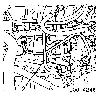
| 19. |
Detach fuel return line (1)
| • |
Unscrew banjo bolt and nut (2)
|
|
|
|
| 20. |
Raise vehicle all the way
|
| 21. |
Detach oil return hose (1)
|
|
|
|
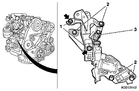
| 22. |
Remove 2 blank holders
| • |
Unscrew 2 stud bolts (arrows)
|
| • |
Disconnect 6 wiring harness plugs
|
| • |
Remove fuel line spacer (3)
|
|
|
Important: Be sure not to damage
the high pressure line (2)
|
| 23. |
Detach high pressure line (1) from high pressure pump at
accumulator
| • |
Remove union nut from accumulator using KM-812 and from high pressure pump using KM-6098
|
| • |
Seal connection of high pressure pump
|
|
|
|
|
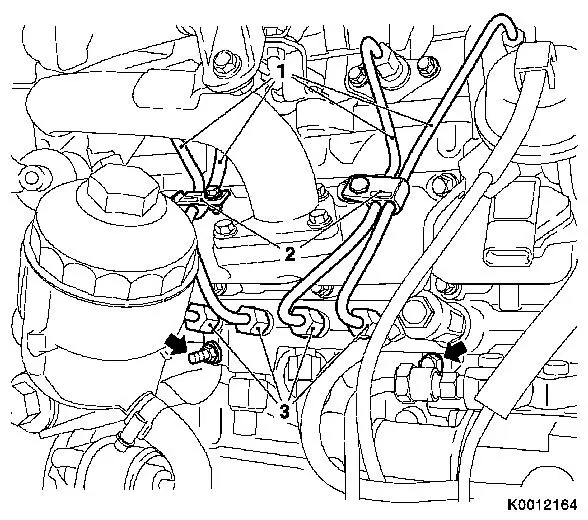
| 24. |
Detach 4 high pressure lines (1) from accumulator to
injectors
| • |
Unscrew 8 union nuts (3)
Note: Seal off the high
pressure lines and injectors
|
| • |
Remove 2 high pressure line spacers (2)
|
|
| 25. |
Remove accumulator
Note: Note differing
bolts
| • |
Unscrew 2 bolts (arrows)
|
|
|
 Install
| 26. |
Install accumulator
Note: Note different
lengths of bolts and spacer sleeves
| • |
Attach fuel return line
| – |
From high pressure pump to accumulator
|
|
|
| 27. |
Install fuel return line
Note: Note differing
bolt lengths
| • |
Attach 4x fuel return line to injectors
|
| • |
Attach fuel return line to accumulator
|
|
| 28. |
Attach 4 accumulator high pressure lines to injectors
| • |
Hand-tighten 8x union nuts
|
|
| 30. |
Fasten accumulator high pressure lines to injectors
| • |
Tighten 8x union nuts with KM-812 and
KM-6098 25
Nm
Note: First tighten
union nuts at the injectors and then at the accumulator
| |
Diameter
|
Torque
|
|
Version 1
|
6.00 mm
|
30 Nm
|
|
Version 2
|
6.35 mm
|
25 Nm
|
|
|
| 31. |
Detach high pressure line from high pressure pump at
accumulator
| • |
Remove 2 protective caps
|
| • |
Tighten 2 union nuts 25 Nm
|
|
| 32. |
Fit 2 blank holders
| • |
Connect 6x wiring harness plugs
|
|
| 33. |
Attach oil return line
|
| 34. |
Lower vehicle all the way
|
| 35. |
Install oil filter housing cover
|
| 36. |
Attach fuel return line
| • |
Attach to accumulator using new gaskets
|
| • |
Attach to intake manifold
|
|
| 37. |
Install charge air pipe
| • |
Tighten 3 bolts 24.5 Nm
|
| • |
Tighten 3 stud bolts 24.5 Nm
|
|
| 38. |
Connect engine wiring harness
| • |
Connect wiring harness plug of charge pressure sensor
|
| • |
Connect wiring harness plug of vacuum unit switchover valve
|
| • |
Connect 4 wiring harness plugs for glow plugs
|
| • |
Connect 4 injector wiring harness plugs
|
|
| 39. |
Install engine control unit bracket support
|
| 40. |
Install engine control unit bracket
|
| 41. |
Install engine control unit
| • |
Connect wiring harness plug
|
|
| 42. |
Install air intake manifold
| • |
Attach engine vent hose to camshaft housing
|
| • |
Attach air intake pipe to turbocharger
|
|
| 43. |
Remove engine management wiring harness
| • |
Connect 3 wiring harness plugs
|
| • |
Connect ground cable to engine control unit
|
|
| 44. |
Attach charge air hose to throttle valve connection
|
| 45. |
Install coolant compensation tank
| • |
Install body-bound rivet
|
|
| 46. |
Attach fuse holder to bracket
|
| 47. |
Install air cleaner housing
| • |
Install air intake hose
|
| • |
Connect wiring harness plug of mass air flow meter
|
|
| 48. |
Install engine cover.
| • |
Detach oil filler port cover
|
| • |
Attach oil filler port cover
|
|
| 49. |
Top up coolant and adjust coolant level
|
| 50. |
Connect battery
| • |
Attach ground clamp to ground terminal
|
|
Important: Wear protective
goggles
|
| 51. |
Carry out leak test on high pressure system
Note: Engine must be at
operating temperature
| • |
Carry out actuator test (fuel leak)
|
| • |
Inspect high pressure system for fuel leak
|
|
| 52. |
Program volatile memory
|
|
