|
J491700 Injection Pump, Replace (Y 17 DTL, without
AC, LHD)
Note: KM-6394 must be used from model year 04 instead of
KM-6169-1 .
|
1. Open bonnet
|
|
Caution!
On vehicles from model year 04 with ESP - the steering angle
sensor loses its basic adjustment each time the battery is
disconnected. It must be recalibrated.
2. Disconnect battery
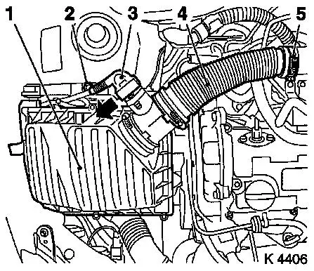
3. Remove air cleaner housing (1)
- Remove wiring harness plug for hot film mass air flow meter
(3)
- Release in direction of arrow
- Remove air intake hose (4)
- Remove bolt (2)
4. Loosen front right wheel
5. Raise vehicle
6. Remove front right wheel
7. Raise vehicle
|
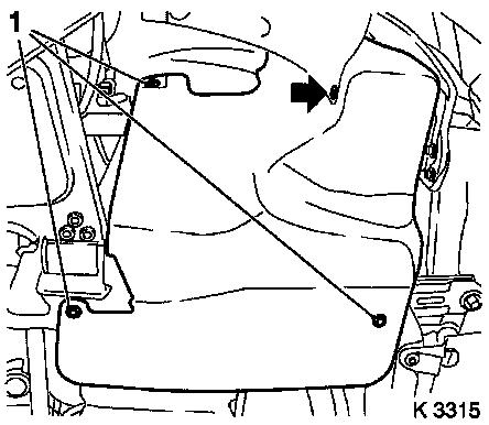
8. Remove ribbed V-belt cover
- Remove 3 bolts (1)
- Remove clip (arrow).
|
|
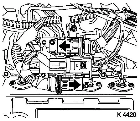
|
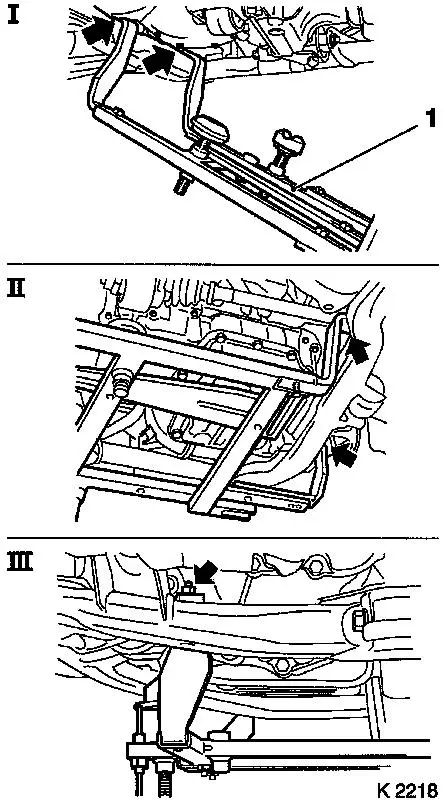
9. Attach KM-6169 (1)
- Place left of KM-6169 onto front axle body (arrows, illus.
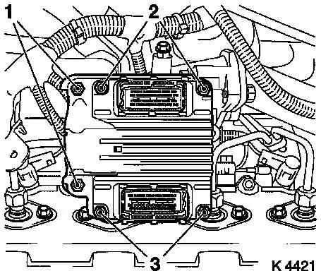
I)
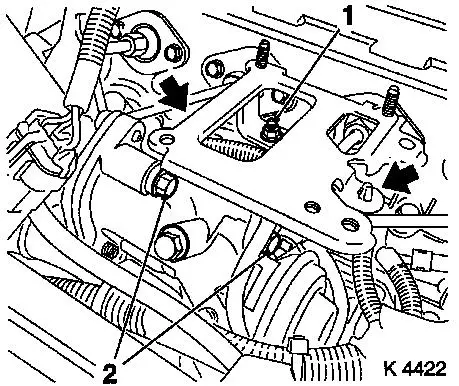
- Note! Guide pin must be seated in bore in front axle body
- Attach both right holders on the front axle body (arrows,
Illus. II).
- Note! Guide pin must be seated in bore in front axle body
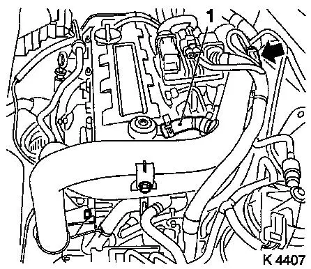
(arrow, Illus. III)
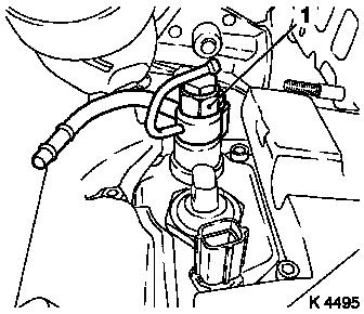
- Tighten bolts
|
|
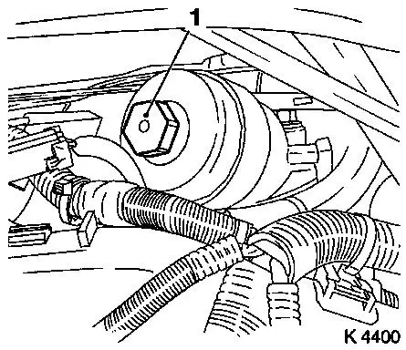
|
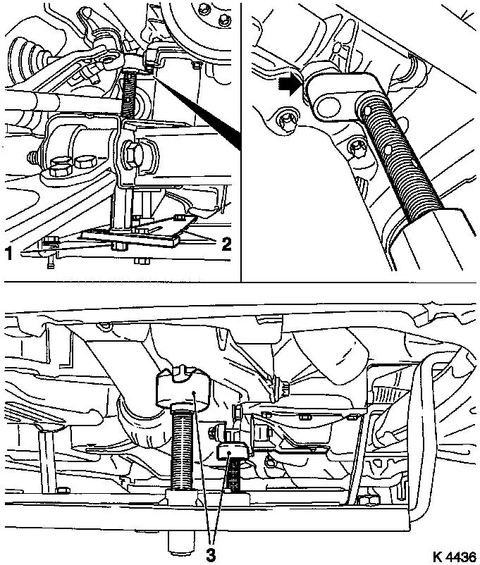
10. Install support
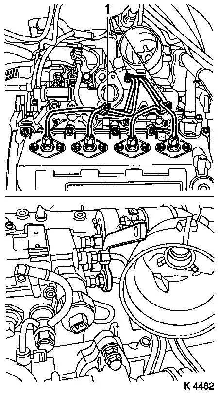
- To KM-6169
- Adjust bracket (2) for support
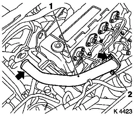
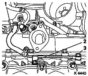
- Screw on nut (1)
|
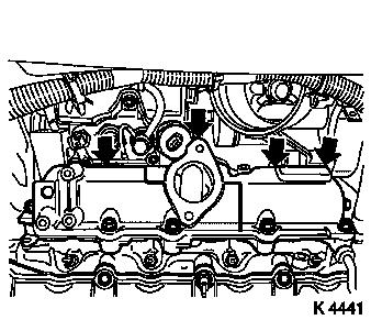
|
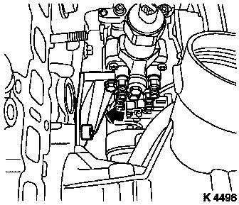
11. Adjust supports
- Transmission side
- Note! Turn spindles until the mounts (3) are positioned at the
guide journals free of play
- Engine timing side
- Insert support pin in cylinder block bore without play
(arrows)
- Tighten nuts (1)
12. Lower vehicle
|
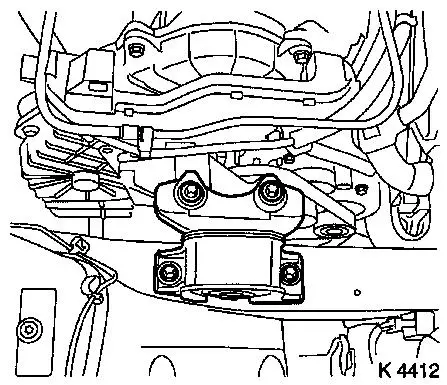
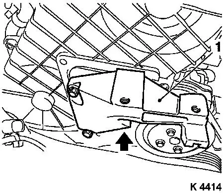
13. Remove right engine damping
block
|
|
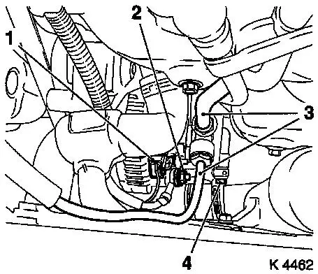
14. Detach alternator wiring
harness
- Disconnect wiring harness plug (1)
- Unscrew nut (2)
|
15. Detach vacuum hoses from vacuum
pump (3)
- Brake servo
- Exhaust gas recirculation solenoid valve
|
|
|
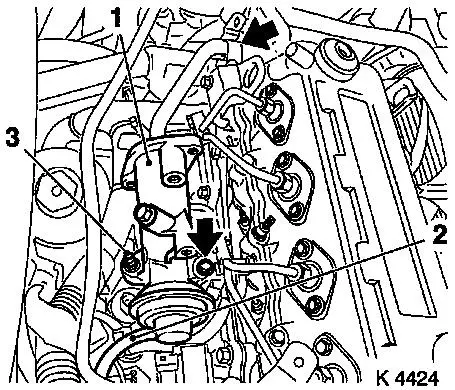
16. Remove wiring trough (1)
- Unclip vacuum lines (2)
- Unclip wiring trough
- Remove bolt (3)
|
|
|
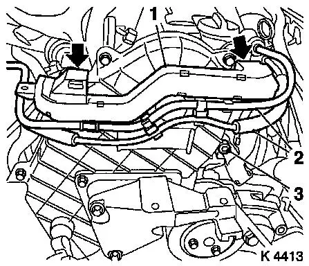
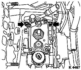
17. Loosen upper part of toothed belt
cover
- Remove 8 bolts
- Note! Note dissimilar bolt lengths
|
|
|
18. Detach right engine bracket (1)
- Remove 3 bolts
- Remove right engine bracket, right engine bracket adapter,
upper part of toothed belt cover
|
|
19. Raise vehicle
|
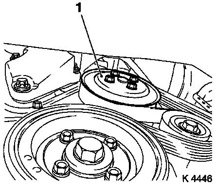
20. Loosen coolant pump ribbed V-belt
pulley (1)
|
|
21. Remove ribbed V-belt
- Tension ribbed V-belt tensioner in direction of arrow
- With KM-913-A
- Note! Mark running direction
22. Detach coolant pump ribbed V-belt
pulley
|
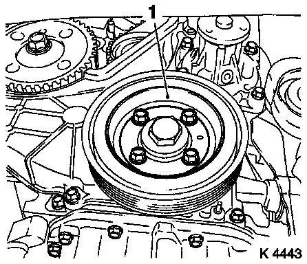
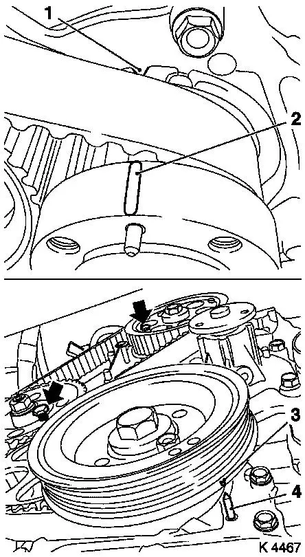
23. Remove torsional vibration damper
(1)
|
|
|
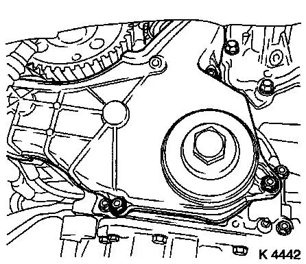
24. Detach lower part of toothed belt
cover
|
|
|
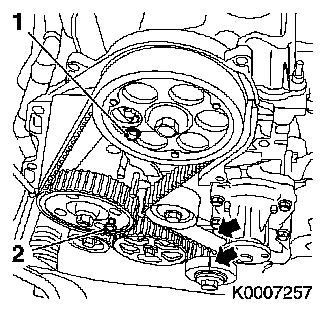
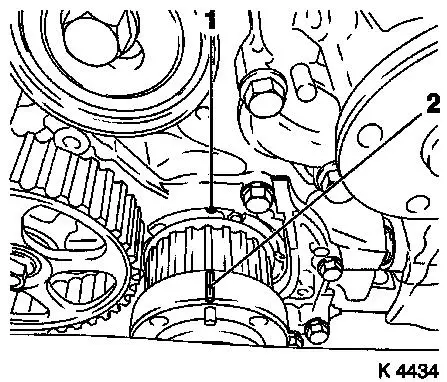
25. Set 1st cylinder to TDC
- Turn crankshaft evenly until TDC-fixing bolts can be
inserted
- Camshaft gear (M6) (1)
- Injection pump gear (M8) (2)
- Note! The mark on toothed belt drive gear must align with lug
on oil pump cover (arrows)
|
|
26. Lower vehicle
|
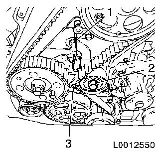
27. For toothed belt tension roller
with leaf spring:
- loosen toothed belt tensioner
- Screw in bolt (M10) in lower bore (3) of toothed belt
tensioner
- Loosen bolt (2)
- Remove tension spring (1)
|
|
|
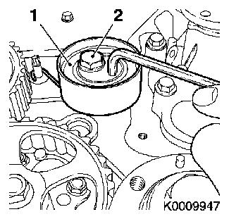
For toothed belt tension roller with
spiral spring:
- Loosen toothed belt tension roller (1)
- Rotate toothed belt tension roller anticlockwise approx.
90°
- Tighten bolt (2)
|
|
28. Remove toothed belt
- Mark direction of rotation
|
29. Remove injection pump gear
- Unscrew nut
- Unscrew TDC-fixing bolt
- Attach KM-6099
- Pull off injection pump gear
- Note! Note woodruff key
|
|
|
30. Remove wiring harness plug for
engine control unit
- 3 off
- Release 2 wiring harness plugs in direction of arrow
- Unclip wiring harness
|
|
|
31. Remove air intake pipe
- Remove 3 bolts
- Remove vent hose (1)
- Detach air intake pipe from turbocharger
|
|
32. Remove charge air hose
- From turbocharger, centre charge air pipe
|
33. Remove engine control unit
- Unclip wiring harness for engine management
- Remove wiring harness plug bracket
- Unscrew 2 bolts (2), 2 nuts (3)
|
|
|
34. Remove engine control unit
bracket
- Unscrew 2 bolts (2), nut (1)
- Unclip wiring harness (arrows)
|
|
35. Detach starter/alternator wiring
harness bracket
- From exhaust recirculation valve
- Remove 2 nuts
|
36. Remove centre charge air pipe
(1)
|
|
37. Remove wiring harness plug
- from sheathed glow plugs
- 4 off
|
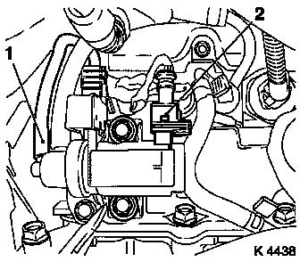
38. Remove exhaust recirculation valve
(1)
- Remove exhaust recirculation pipe
- Unscrew studs (3), 2 bolts
- Detach vacuum hose (2)
- Remove gaskets
|
|
|
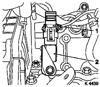
39. Remove exhaust recirculation
solenoid valve
- Detach vacuum hose (1)
- Detach wiring harness plug (2).
- Remove 2 bolts
|
|
40. Remove right rear engine transport
shackle
|
41. Remove charge pressure sensor
(2)
- Disconnect wiring harness plug (1)
- Remove bolt
|
|
|
42. Remove oil filter insert
- Place collecting basin underneath.
- Unscrew oil filter housing cover (1)
|
|
43. Detach oil return line
- From oil filter housing
- Release clamp
|
44. Remove injection line spacers
(1)
|
|
45. Remove injection lines
|
46. Detach outer oil leak line
- Unscrew 1 banjo bolt (3), 1 bolt (2)
- Remove oil leak hose (1)
|
|
47. Remove wiring harness plug
- From diesel injection pump
|
48. Remove two piece intake
manifold
- Unscrew 7 bolts, 2 nuts
- Remove gaskets
|
|
49. Remove fuel lines
- From diesel injection pump
|
50. Remove fuel return connection
- Note! Do not unscrew check valve (SW 14) from banjo bolt.
Carefully unscrew banjo bolt (1) (SW 17)
- Close off return bore using blind plugs
|
|
51. Remove outer diesel injection pump
insulation
52. Remove wiring harness for engine
management
- Disconnect wiring harness plug
- Unclip wiring harness
53. Remove inner diesel injection pump
insulation
|
54. Remove diesel injection pump
bracket
|
|
|
55. Remove diesel injection pump
- Remove 2 nuts
- Disconnect wiring harness plug
|
|
56. Install diesel injection pump
- Insert diesel injection pump
- Connect wiring harness plug.
- Tighten 2 nuts with washers (19.6 Nm/14.5 lbf. ft.)
57. Install diesel injection pump
bracket
- Install 4 bolts
- Tighten 2 bolts at cylinder head (53.9 Nm / 39.8 lbf. ft.)
58. Install injection pump gear
Note: Observe
tightening sequence
| 1. |
Tighten nut 60 Nm
|
| 2. |
Loosen nut |
| 3. |
Waiting time: 60 sec |
| 4. |
Tighten nut 60 Nm
|
| |
o |
Install TDC-fixing bolt |
|
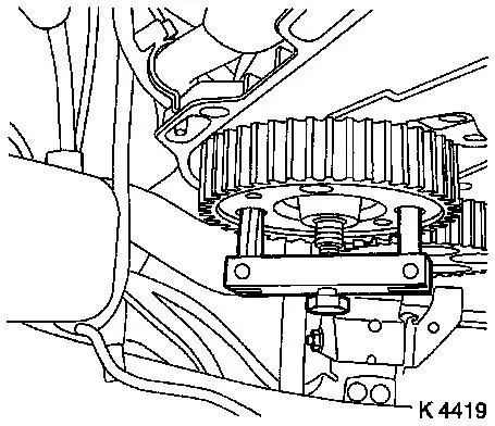
59. Check TDC position for 1st
cylinder
- Mark on toothed belt drive gear (2) must align with casting lug
at oil pump cover (1)
|
|
60. Install toothed belt
Note: Toothed belt
must be taut from toothed belt drive gear via oil pump drive gear
and injection pump drive gear
- For toothed belt tension roller with leaf spring:
- Unscrew TDC-fixing bolt
- Rotate crankshaft 60° against direction of engine
rotation
- Tighten bolt of toothed belt tension roller
- For toothed belt tension roller with spiral spring 49 Nm
- For toothed belt tension roller with leaf spring 38.2 Nm
61. For toothed belt tension roller with leaf spring: unscrew
bolt (M10) from lower bore of toothed belt tensioner
|
62. Timing, Check
- Turn crankshaft approx. 780° in direction of engine
rotation
- At toothed belt drive gear bolt
- Mark on toothed belt drive gear (2) must align with casting lug
at oil pump cover (1)
- Install TDC-fixing bolt
- Install torsional vibration damper
- Note! Mark on torsional vibration damper (3) must align with
pin (4) on oil pump cover If the TDC fixing bolts cannot be
inserted, the basic adjustment must be repeated
- Unscrew TDC-fixing bolts
|
|
|
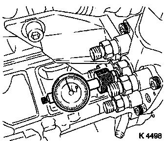
63. Attach KM-798
- Turn crankshaft in direction of engine rotation to 45°
before 1st cylinder TDC
- At toothed belt drive gear bolt
- Remove central bleeder screw
- Install KM-798 under pre-tension
- Determine BDC position of injection pump plunger by turning
crankshaft back and forth
- Note! The dial gauge indicator must not move
- Set dial gauge to "0".
|
|
64. Adjust diesel injection pump
- Turn crankshaft to 1st Cylinder TDC
- Note! The pin on the oil pump must align with the mark on the
pulley
- Loosen diesel injection pump
- Turn diesel injection pump until 0.33 mm adjustment value is
accomplished
- Value too high – turn injection pump towards engine.
- Value too low – turn injection pump away from
engine.
- Tighten diesel injection pump (19.6 Nm / 14.4 lbf. ft.)
65. Check start of feed
- Remove KM-798
- Turn crankshaft approx. 675°
- Install KM-798 under pre-tension
- Determine BDC position of injection pump plunger by turning
crankshaft back and forth
- Note! The dial gauge indicator must not move
- Set dial gauge to "0".
- Turn crankshaft to 1st Cylinder TDC
- Note! The pin on the oil pump must align with the mark on the
pulley
- Read test value
- Test value: 0.28 – 0.38 mm
- Caution! If test value is not achieved, adjustment must be
repeated
66. Remove KM-798
- Remove dial gauge
- Tighten centre bleeder screw (25 Nm / 18.4 lbf. ft.)
67. Install diesel injection pump
bracket
- Tighten 2 bolts (18.6 Nm / 13.7 lbf. ft.)
68. Remove torsional vibration
damper
69. Insert inner diesel injection pump
insulation
70. Attach wiring harness for engine
management
- Connect wiring harness plug.
- Attach wiring harness
71. Install outer diesel injection pump
insulation
72. Attach fuel line connection
73. Attach fuel lines
74. Clean sealing surfaces
75. Install two piece intake
manifold
- Replace gaskets
- Tighten bolts, nuts (24.5 Nm/18.7 lbf. ft.)
76. Connect wiring harness plug
77. Install outer oil leak line
- Renew seal rings
- Tighten bolt, banjo bolt (14.7 Nm / 10.8 lbf. ft.)
- Install oil leak hose
78. Install injection lines
- Caution! Injection lines must be installed without tension.
Hand-tighten at injector nozzles and injection pump.
- Tighten union nuts (22.5 Nm/16.6 lbf. ft.)
79. Install injection line spacers
- Note! Note spacer positions
- 3 off
80. Attach oil return line
81. Install oil filter insert
- Replace seal ring
- Tighten oil filter housing cover (25 Nm/18.5 lbf. ft.)
82. Install charge control sensor
- Tighten bolt (9.8 Nm / 7.2 lbf. ft.)
- Connect wiring harness plug.
83. Install exhaust recirculation
solenoid valve
- Rework threads
- Tighten 2 bolts
- Insert bolts with locking compound
- Connect wiring harness plug.
- Connect vacuum hose.
84. Install right rear engine transport
shackle
- Tighten bolt (20 Nm / 15 lbf. ft.)
85. Install exhaust recirculation
valve
- Clean sealing surfaces.
- Insert exhaust recirculation valve
- Tighten studs, 2 bolts (24.5 Nm/18.1 lbf. ft.)
- Replace gasket
- Connect vacuum hose.
- Attach exhaust gas recirculation pipe
- Tighten 2 bolts (28.4 Nm / 21 lbf. ft.)
- Replace gasket
86. Install centre charge air pipe
- Clean sealing surface
- Tighten studs, 2 bolts
- Replace gasket
87. Attach starter/alternator wiring
harness bracket
88. Attach wiring harness plug
89. Install engine control unit
bracket
- Tighten 2 bolts (24.5 Nm / 18 lbf. ft.)
- Tighten nut (9.8 Nm/7.2 lbf. ft.)
- Clip in wiring harness
90. Install engine control unit
- Install engine control unit
- Tighten 2 bolts, 2 nuts (5.9 Nm/4.4 lbf. ft.)
- Install wiring harness plug bracket
- Connect wiring harness plug.
91. Install air intake pipe
- Tighten 3 bolts
- Fasten hose clamp
- Attach engine vent hose
- Attach wiring harness
92. Attach charge air hose
93. Attach engine control unit wiring
harness plug
- Route wiring harness
- Connect wiring harness plug.
- Attach wiring harness
94. Attach lower part of toothed belt
cover
- Tighten bolts (9.8 Nm / 7.2 lbf. ft.)
95. Attach right engine bracket
- Insert lower bolt
- Into right engine bracket and right engine bracket adapter
- Insert right engine bracket, right engine bracket adapter,
upper part of toothed belt cover
- Install 2 upper bolts
- Tighten 3 bolts (40 Nm / 29.5 lbf. ft.)
96. Fasten upper part of toothed belt
cover
- Tighten bolts (9.8 Nm / 7.2 lbf. ft.)
- Note! Note dissimilar bolt lengths
97. Attach coolant pump ribbed V-belt
pulley
98. Raise vehicle
99. Install torsional vibration
damper
- Tighten bolts (19.6 Nm / 14.5 lbf. ft.)
100. Install ribbed V-belt
- Note! Observe running direction and installation position
- Release ribbed V-belt tensioner
101. Fasten coolant pump ribbed V-belt
pulley
- Tighten bolts (9.8 Nm / 7.2 lbf. ft.)
102. Lower vehicle
103. Install right engine damping
block
- To side member
- Tighten bolts (40 Nm / 29.5 lbf. ft.)
- On engine bracket
- Tighten bolts (60 Nm/44 lbf. ft + 30° + 15°.)
104. Attach wiring trough
- Clip-in wiring trough
- Clip in vacuum lines
- Tighten bolt
105. Attach alternator wiring
harness
- Connect wiring harness plug.
- Tighten nuts
106. Install vacuum hoses from vacuum
pump
- Route lines and clip in
- Tighten union nut (18 Nm/13.3 lbf. ft.)
107. Install air cleaner housing
- Tighten bolt
- Fasten air intake hose.
- Connect wiring harness plug to hot film mass air flow
meter
108. Raise vehicle
109. Detach support
110. Remove KM-6169
111. Install ribbed V-belt cover
- Screw in bolts
- Install clip
112. Lower vehicle
113. Install right front wheel
114. Lower vehicle
115. Fasten right front wheel
- Tighten bolts (110 Nm / 81 lbf. ft.)
116. Connect battery
117. Calibrate steering angle sensor
Note: Rotate the
steering wheel one time from its right-hand to its left-hand
stop.
118. Top up engine oil
- Observe specified engine oil quantity
- Start engine and allow to run until oil pressure telltale
extinguishes.
- Check engine oil level, if necessary correct.
119. Program volatile memories
120. Close bonnet
|
