|
Overhaul multi-plate clutch C0 and C3
(AF13-II)
 Remove Remove
| 1. |
Remove multi-plate clutch assembly C0 and C3 
|
|
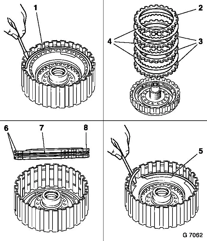
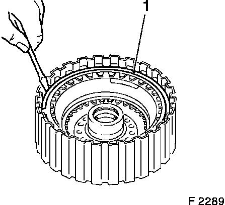
| 2. |
Remove retaining ring (1) for multi-plate clutch C0 with
suitable screwdriver
|
| 3. |
Remove flange (2) lining plates (4) and steel plate (3)
|
| 4. |
Remove retaining ring (5) for multi-plate clutch C3 with
suitable screwdriver
|
| 5. |
Remove flanges (6), lining plates (7) and steel plate (8)
|
|
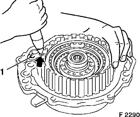
|
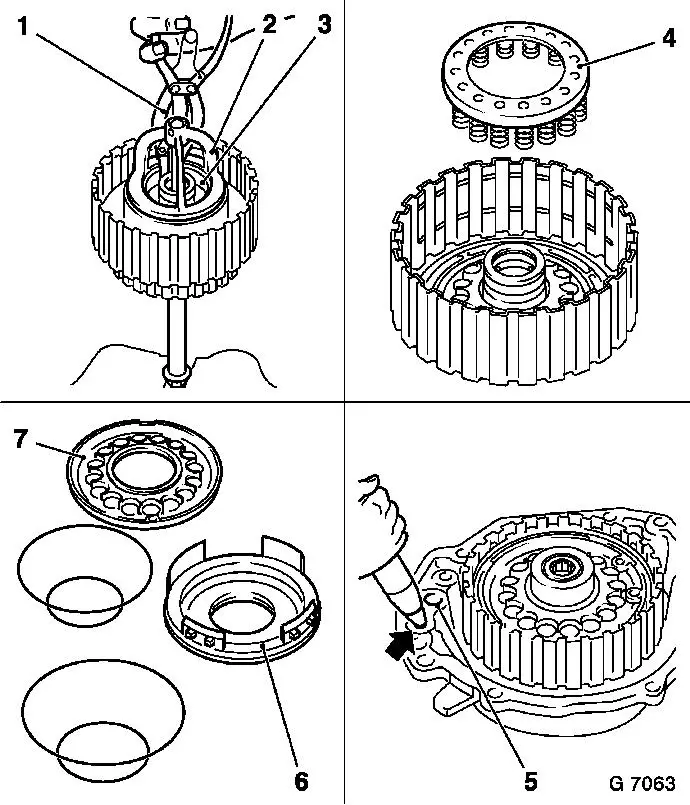
| 6. |
Fit KM-J-23078-A (2) with KM-620-2 (3)
| • |
Clamp nut in vice for tensioning
|
|
| 7. |
Remove retaining ring with KM-396
(1)
| • |
Rotate housing for multi-plate clutch C0 and C3 (compress
release springs)
|
| • |
Expose retaining ring
| – |
Relieve stress on KM-J-23078-A and
detach
|
|
|
| 8. |
Remove return spring assembly (4)
|
| 9. |
Insert housing with piston for multi-plate clutch C0 and C3 in
the multi-plate clutch assembly C1 and rear cover
Note: Do not damage
seal rings.
|
| 10. |
Remove pistons C3 and C0
| • |
Blow air at low pressure into bore C3 (arrow) and C0 (5)
|
|
| 11. |
Replace piston seal rings of piston C0 (6) and piston C3
(7)
Note: Coat with
transmission fluid before installation.
|
|
 Install
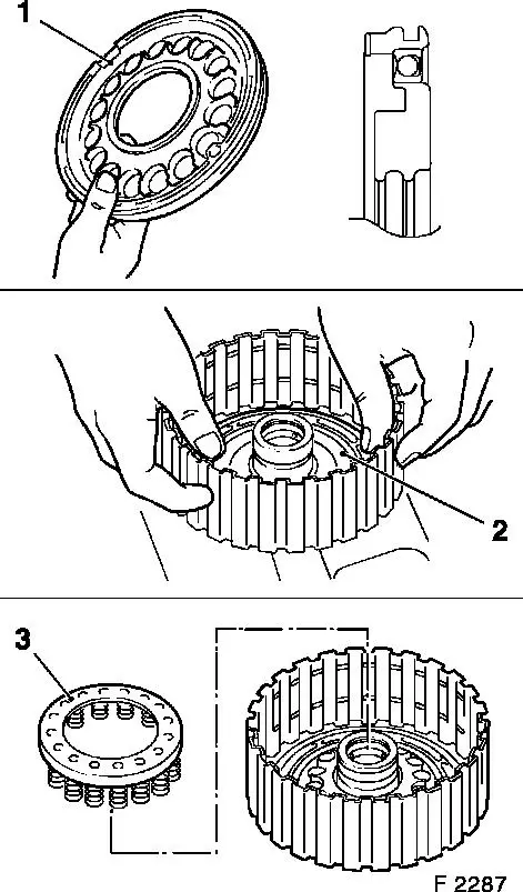
| 12. |
Check lock ball of piston (1) for multi-plate clutch C3
| • |
Check whether lock ball can move by shaking the piston
|
|
| 13. |
Check return spring assemblies (C0 and C1) for damage
Note: Replace if
necessary.
|
| 14. |
Check sliding surfaces of the steel and liner plates for damage
and wear
Note: Replace if
necessary.
Place new liner plates in transmission fluid for at least 2 hours
before installation
|
| 15. |
Insert piston C0 (2) into housing for multi-plate clutch C0 and
C3 with new O-rings
| • |
Do not damage O-rings
Note: Proceed in same
way for piston C3.
|
|
| 16. |
Place return spring assembly (3) onto piston C3
| • |
Attach new retaining ring
|
|
|
|
|
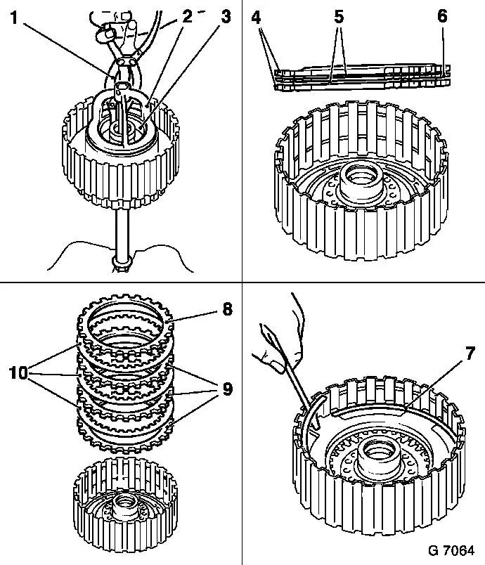
| 17. |
Compress return springs
| • |
Attach KM-J-23078-A (2) with KM-620-2 (3)
|
| • |
Insert retaining ring with KM-396
(1)
|
| • |
Relieve stress on KM-J-23078-A and
detach
|
|
| 18. |
Insert flanges (4), liner plates (5) and steel plate (6)
|
| 19. |
Insert new retaining ring (7) with screwdriver
|
| 20. |
Insert flange (8), liner plates (10) and steel plate (9)
Note: Number of steel
and liner plates
|
|
| 21. |
Insert new retaining ring (1) with screwdriver
Note: Ensure it is
correctly seated.
|
|
|
| 22. |
Insert multi-plate clutch assembly C0 and C3 in multi-plate
clutch assembly C1 and rear cover
Note: Do not damage
seal rings.
|
| 23. |
Check operation of pistons C0 and C3
| • |
Blow compressed air into bore for C0 (arrow) and C3 (1) on rear
cover
|
|
| 24. |
Install multi-plate clutch assembly C0 and C3
|
|
|
|
