|
Replace shift module (F13 MTA/F17+ MTA)
Note: A foreign power
supply could damage the shift module. In order to ensure correct
appraisal, a dismantled shift module must never be reassembled.
 Remove Remove
| 1. |
Put transmission into neutral
| • |
Depress foot brake and shift the selector lever to position
"N"
|
|
| 2. |
Remove crash box
| • |
only Z 13 DT and Z 13 DTJ
|
|
| 3. |
Remove charge air pipe
| • |
only Z 13 DT and Z 13 DTJ
|
|
|
| 4. |
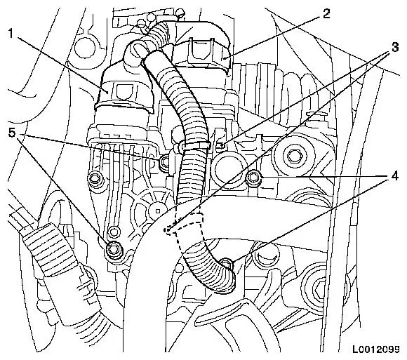
Disconnect 2x wiring harness plugs (1) and (2) from shift
module
| • |
Detach 2x cable ties (3)
|
|
| 5. |
Remove shift module
| • |
Unscrew 4x bolts (4) and (5)
|
| • |
Lift the shift module, tilt it forwards, remove
|
|
|
|
Important: If it cannot be
removed in this way, e.g. because of a fault, proceed as follows:
Remove selector motor and gearshift motor individually. Once
disassembled, the gearshift module cannot be re-used and must be
replaced.
|
| 6. |
Remove selector motor and gearshift motor individually
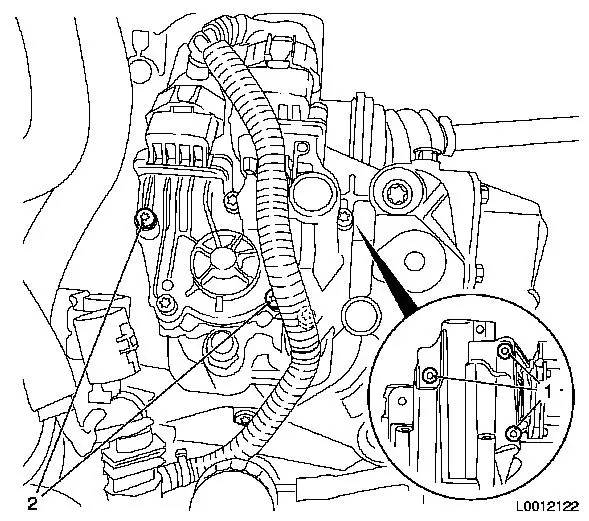
Note: Only if shift
module is faulty.
| • |
Remove selector motor
| – |
Unscrew 3x bolts (1) and remove selector motor
|
|
| • |
Remove gearshift motor
| – |
Unscrew 2x bolts (2) and remove gearshift motor
|
|
|
|
|
| 7. |
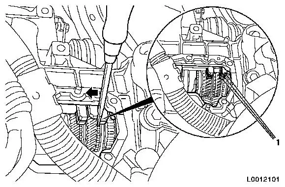
Put transmission into neutral
Note: Only required if
shift module is faulty.
| • |
Bring shift forks into idle position with screwdriver
Note: All 3 shift forks
(1) must align and reverse gear must not be engaged.
|
|
|
| 8. |
Clean sealing surfaces
| • |
Clean sealing surfaces and threaded holes for shift module
|
|
 Install
Important: The following step is
only required up to production status G4D4 001 05 b of the shift
module. The production status is shown on the sticker on the shift
module housing. From production status G4D4 001 05 c onwards the
marking stamped on the gearshift motor pinion toothed head has been
discontinued. Where the production status of the shift module (e.g.
G4D4 001 03 e) is stamped there, it is absolutely essential for the
markings to agree, otherwise there will be entries in the fault
memory and/or system failures.
|
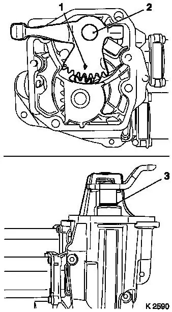
| 9. |
Align the marking (1) on the gearshift lever shaft (2) with the
toothed head of the pinion, gearshift motor
| • |
Move gearshift lever shaft to the idling position
Note: Groove (3) is
visible.
|
|
| 10. |
Insert transmission shift module
|
|
|
|
| 11. |
Install shift module
| • |
Fit shift module with new gasket
|
| • |
Tighten 4x bolts (4) and (5) 11
Nm
Note: Use new
bolts.
|
| • |
Connect 2x wiring harness plugs (1) and (2)
Note: Wiring harness
plug 1 - black (gearshift motor), wiring harness plug 2 - grey
(selector motor).
|
| • |
Attach 2x cable ties (3)
|
|
|
| 12. |
Install charge air pipe
| • |
only Z 13 DT and Z 13 DTJ
|
|
| 13. |
Install crash box
| • |
only Z 13 DT and Z 13 DTJ
|
|
| 14. |
Match transmission parameters 
|
| 15. |
Comply with the start-up routines required
|
|
