|
Main shaft, dismantle and assemble (F13/F13
MTA)
Note: Transmission
remains installed.
 Remove Remove
|
| 1. |
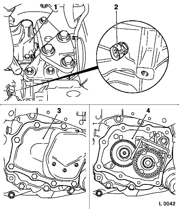
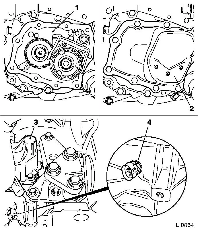
Remove gearshift cover (1)
|
| 2. |
Remove reversing lamp switch (2)
|
| 3. |
Remove end shield cover (3) gasket 
|
| 4. |
Remove end shield (4) from transmission
|
|
|
| 5. |
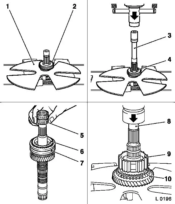
Remove main shaft
Note: If the gears are
damaged, always also replace the gear cluster.
|
| 6. |
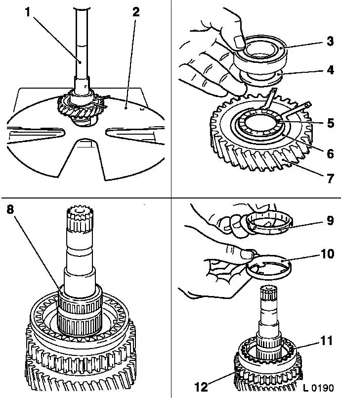
Push off ball bearing (3), spacer washer (4), retaining ring
(6), axial needle bearing (5) and 1st gear gearwheel (7) with KM-307-B (2)
|
| 7. |
Remove needle bearing (8) for 1st gear gearwheel from main
shaft
|
| 8. |
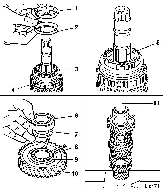
Remove inner synchro ring (9), intermediate ring (10) and outer
synchro ring (11) for 1st gear gearwheel from synchroh body
assembly (12)
|
|
|
| 9. |
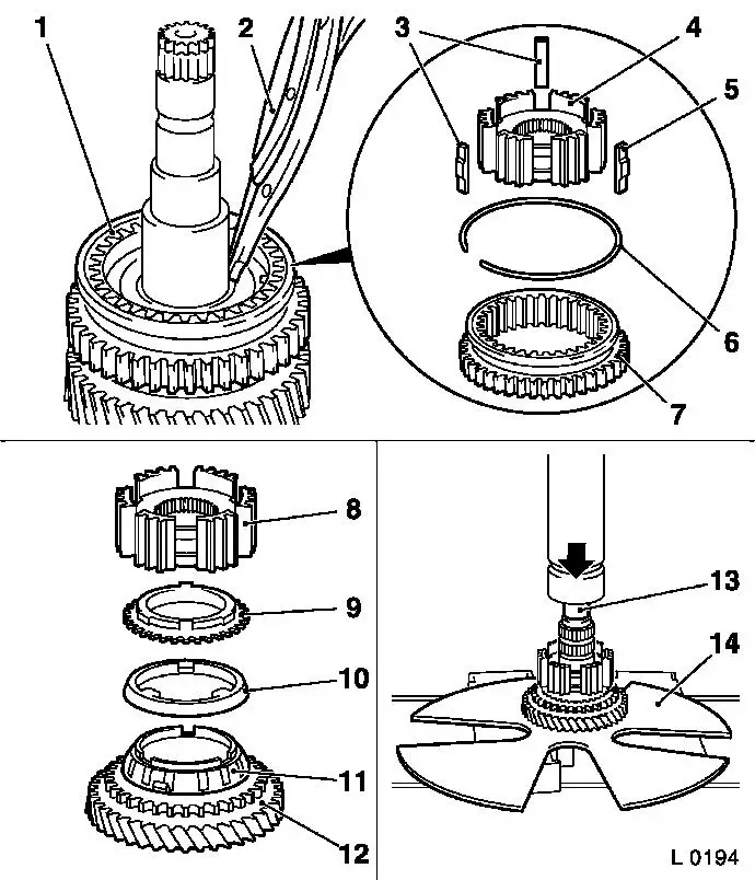
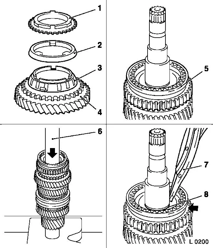
Remove retaining ring for 1st/2nd gear synchro body assembly
(1) with circlip pliers (2)
|
| 10. |
Remove shift sleeve (7), synchro spring (6) and sliding blocks
(3 and 5) from synchro body (4)
|
| 11. |
Push synchro body (8), inner synchro ring (9), intermediate
ring (10) and outer synchro ring (11) for 2nd gear gearwheel (12)
from main shaft with KM-307-B (14)
| • |
Use suitable drift (13)
|
|
|
|
| 12. |
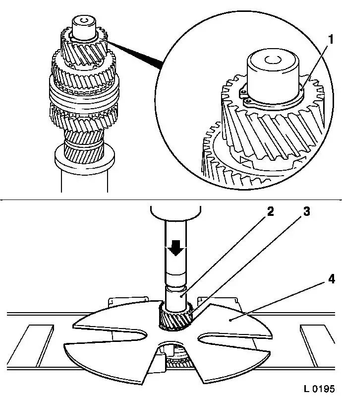
Remove retaining ring (1) in front of drive gear (driving) from
main shaft
|
| 13. |
Push drive gear (driving) (3) from main shaft with KM-307-B (4)
Note: Always replace
drive gears (driving and driven) in pairs
|
|
|
| 14. |
Place KM-307-B (1) in groove of 4th
gear gearwheel (2)
|
| 15. |
Push 4th gear gearwheel and spacer washer (4) from main shaft
with KM-307-B
|
| 16. |
Remove needle bearing (5) (if present), synchro ring (4th gear
gearwheel) (6), shift sleeve (7), synchro spring and sliding blocks
from main shaft
|
| 17. |
Push 3rd/4th gear synchro body (9), synchro ring and 3rd gear
gearwheel (10) from main shaft with KM-307-B
|
|
 Install
|
| 19. |
Immerse all parts in transmission fluid before
installation.
|
| 20. |
Check all removed parts for damage and wear, replace if
necessary
|
| 21. |
Lubricate all bearing bore holes and seating surfaces with
transmission fluid before installation.
|
| 22. |
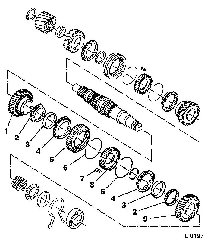
Transmission has 3 cone synchronisation for 1st/2nd gear:
| 1. |
2nd speed gear |
| 2. |
Inner synchroniser rings |
| 3. |
Intermediate rings |
| 4. |
Outer synchroniser rings |
| 5. |
Shift sleeve |
| 6. |
Synchroniser springs |
| 7. |
Sliders |
| 8. |
Synchromesh body |
| 9. |
1st speed gear |
|
|
|
| 23. |
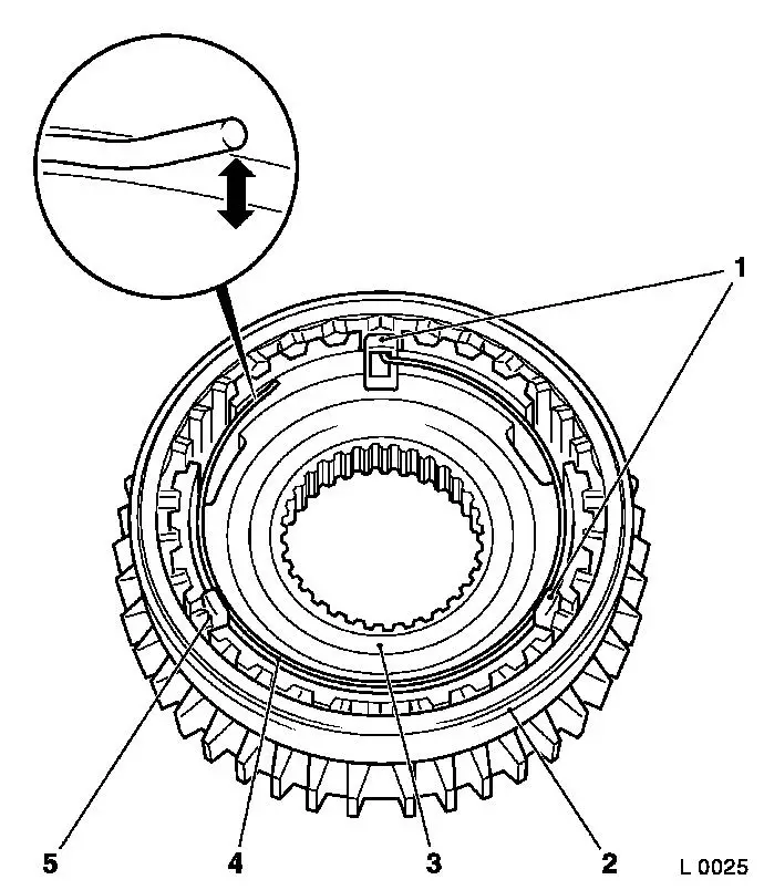
Insert synchro body (3) in shift sleeve (2)
Note: Synchromesh body
assembly 1st/2nd gear and 3rd/4th gear can only be pressed onto
main shaft in assembled state.
|
| 24. |
Insert sliding blocks (1) and (5)
| • |
with the open side towards the synchro body
|
|
| 25. |
Insert synchroniser spring (4)
Note: Ensure that the
free end is raised from the synchro body (arrow) in the correct
installation position. If this is not the case, turn synchro ring
by 180° and re-install.
| • |
Offset end of synchro spring engages in a sliding block
|
|
|
|
| 26. |
Attach needle bearing (2) for gear wheel, 3rd gear, to main
shaft (1)
Note: If present.
|
| 27. |
Push 3rd gear gearwheel (3) onto main shaft from drive wheel
side
| • |
Cone (arrow) points in direction of drive wheel
|
|
| 28. |
Place synchroniser ring (4) onto 3rd gear cone.
|
| 29. |
Press synchro body assembly for 3rd/4th gear (6) with KM-277 (5) onto main shaft.
|
|

|
| 30. |
Attach needle bearing, gear wheel, 4th gear to main shaft
Note: If present.
|
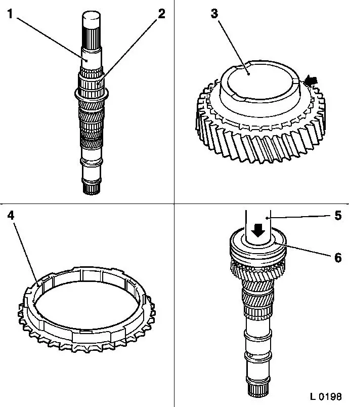
| 31. |
Attach synchro ring (3) and 4th gear gearwheel (2) to main
shaft
|
| 32. |
Place spacer washer (1) onto drive shaft
| • |
Four grooves (arrows) must point towards 4th gear gearwheel
|
|
| 33. |
Press drive wheel (5) onto main shaft with KM-311-2 (4)
Note: Always replace
drive gears in pairs.
| • |
Shoulder must point towards spacer washer
|
|
| 34. |
Fit new retaining ring (6) in front of drive gear
|
|
|
| 35. |
Slide 2nd gear gearwheel (4) onto main shaft
|
| 36. |
Place inner synchro ring (3) onto cone of gearwheel
| • |
Lugs must sit in grooves of gear wheel
|
|
| 37. |
Place intermediate ring (2) onto inner synchro ring
|
| 38. |
Place outer synchro ring (1) onto intermediate ring
| • |
Grooves must sit on lugs of inner synchro ring
|
|
| 39. |
Place synchro body assembly (5) onto main shaft
|
| 40. |
Press synchro body assembly onto main shaft with KM-277 (6)
| • |
Lugs in outer synchro ring must align with grooves in synchro
body
|
| • |
Shift fork groove (arrow) points towards ball bearing seat
|
|
| 41. |
Insert new retaining ring (8) in front of 1st/2nd gear synchro
body with circlip pliers (7)
|
|
|
| 42. |
Place outer synchro ring (3) with lugs in grooves of synchro
body (4)
|
| 43. |
Place intermediate ring (2) onto outer synchro ring
|
| 44. |
Place inner synchro ring (1) onto intermediate ring
| • |
Lugs must engage in grooves of outer synchro ring
|
|
| 45. |
Place 1st gear needle bearing (5) onto main shaft
Note: If present.
|
| 46. |
Slide 1st gear gearwheel onto needle bearing
| • |
Grooves must sit on lugs of intermediate ring
|
|
| 47. |
Place axial needle bearing (8) onto 1st gear gearwheel (10)
| • |
Place spacer washer (7) onto needle bearing
|
|
| 48. |
Place new retaining ring (9) with long legs for main shaft at
end shield onto 1st gear gearwheel
| • |
Press ball bearing (6) onto main shaft with KM-334 (11)
|
|
|
|
| 49. |
All gears must turn easily
|
| 51. |
Install end shield (1) in transmission
|
| 52. |
Install end shield cover (2)
|
| 53. |
Install reversing lamp switch (4) with new seal ring
|
| 54. |
Install gearshift cover (3)
|
|
|
