|
Remove and install manual transmission
(F13/F17/F17 new/F17+)
 Remove Remove
| 1. |
Align drive unit
Note: In order to
ensure that the drive unit is correctly aligned when the left
engine damping block bolts are undone, the drive unit must be
aligned with the front axle body using the KM-6169
|
|
|
| 2. |
Remove crash box
| • |
Z 13 DT / Z 13 DTJ / Z 17 DTH 
|
|
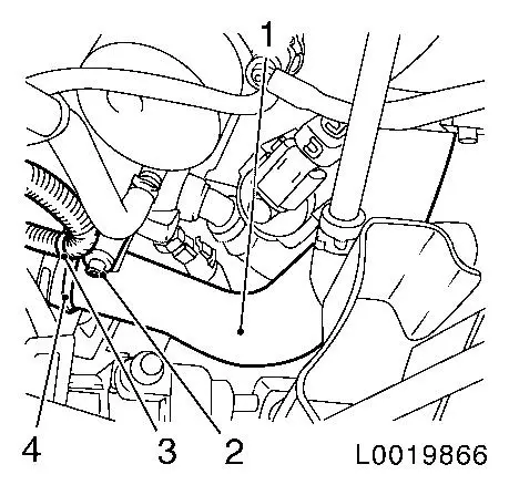
| 3. |
Remove charge air pipe (1)
Note: Only required for
Z 13 DT and Z 13 DTJ.
| • |
Unclip wiring harness (3)
|
|
|
|
| 4. |
Fill brake fluid reservoir to "MAX" mark and seal with MKM-558-10 .
|
| 5. |
Remove upper engine cover
Note: If present.
|
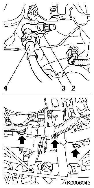
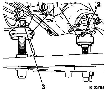
| 6. |
Disconnect pressure line (4) from connector (2) for pressure
line for central release from transmission housing
| • |
Release clamp (3) with screwdriver and remove
|
| • |
Bend clamp together a little and insert back into connector
Note: Collect escaping
brake fluid
|
|
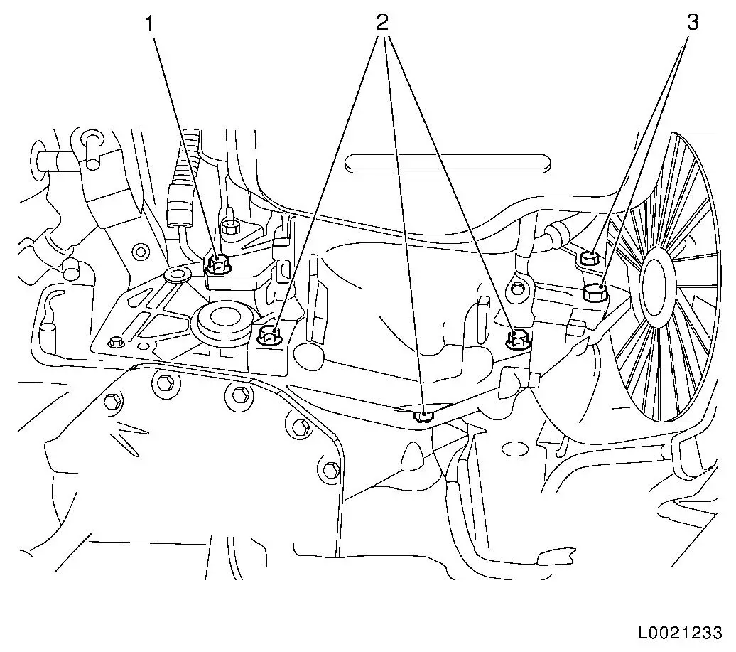
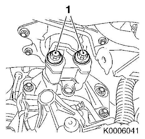
| 7. |
Detach wiring harness plug (1) from reversing lamp switch
|
| 8. |
Disconnect wiring harness plug from coolant temperature
sensor
Release wiring harness plug and disconnect.
Note: Only required for
Z 13 DT and Z 13 DTJ.
|
| 9. |
Remove 3 transmission bolts (arrows)
Note: If necessary pull
coolant pipe upwards and secure with cable ties
|
|
|
| 10. |
Remove front axle body
Note: The tool KM-6169 remains on the front axle body and must
not be adjusted.
|
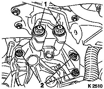
| 11. |
Remove engine damping block retaining bracket
| • |
Remove left engine damping block bolts (1)
|
| • |
Remove 2 bolts (2) for left engine damping block retaining
bracket from transmission
|
|
| 12. |
Lower engine with transmission on MKM-883-1 by approx. 5 cm
Note: Ensure that the
coolant hoses and wiring harnesses are not stretched.
|
| 13. |
Detach shift linkage from shift guide
|
|
|
Important: Fluid escapes. Place
collecting pan underneath and close off apertures with plug.
|
| 14. |
Remove axle shafts from transmission
Note: Axle shafts
remain in wheel hubs.
| • |
Attach axle shafts to vehicle underbody
|
|
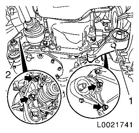
| 15. |
Detach front engine damping block (2) from transmission
Note: If present.
| • |
Unscrew 2x bolt (arrows)
|
|
| 16. |
Detach rear engine damping block bracket (3) from
transmission
| • |
Unscrew 2x bolt (arrows)
|
|
|
|
|
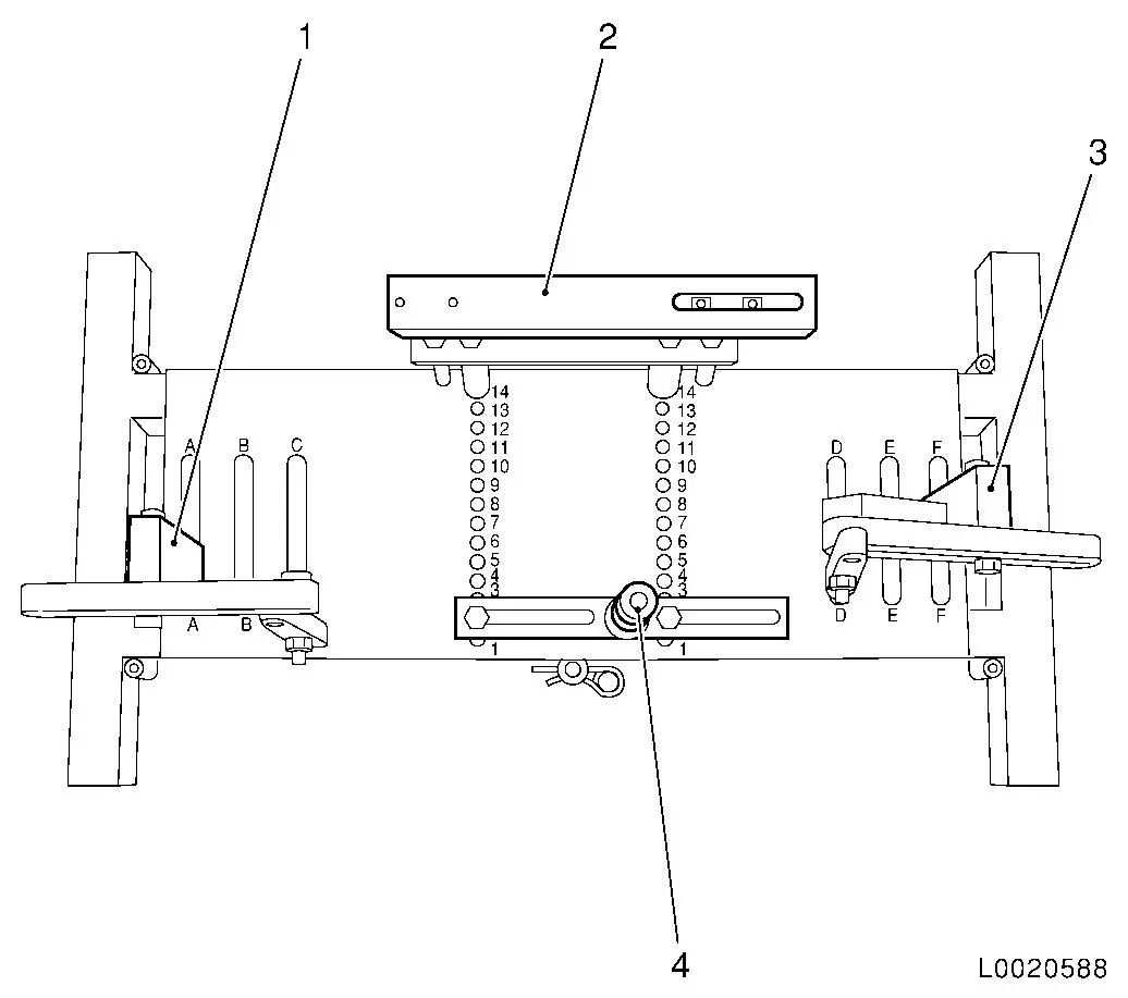
| 17. |
Position transmission holder DT-47648
on KM-904 and preinstall as shown in the
illustration:
|
Component
|
Position on base plate
|
Designation
|
|
DT-47648-2
(4)
|
2
|
Clutch housing support
|
|
DT-47648-3
(2)
|
14
|
Transmission housing support
|
|
DT-47648-5 left
(1)
|
A
|
Support with rear transmission swivel arm
|
|
DT-47648-5 right
(3)
|
F
|
Support with front transmission swivel arm
|
|
|
Important: It is important that
the manufacturer's instructions for transmission holder DT-47648 are followed.
|
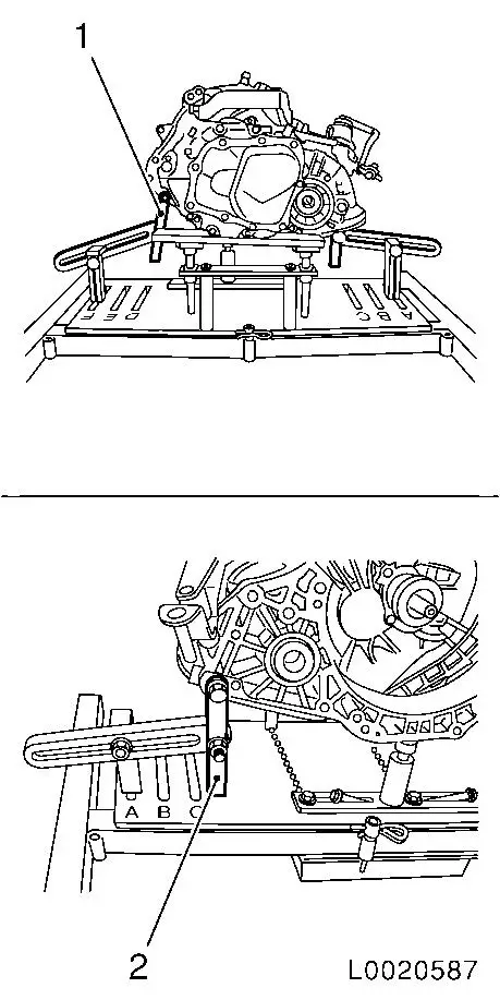
| 18. |
Attach transmission holder DT-47648
to transmission
Note: Before placing in
position, slacken all bolt connections of the swivel arms and
supports as far as the base plate. Adjust the supports using the
spindles until they are as low as possible.
| • |
Position transmission holder DT-47648
and supports under the transmission
|
| • |
Tighten the bolt connections of the supports
|
| • |
Attach swivel arms (1) and (2) to transmission
|
| • |
Tighten bolt connections of swivel arms, starting from the
transmission and going as far as the base plate
Note: Align the swivel
arms so that as little leverage as possible is created.
|
|
|
|
|
| 19. |
Remove transmission
| • |
Unscrew 3x bolts (2), transmission to oil pan
|
| • |
Unscrew 3x bolts (1) and (3), transmission to cylinder
block
Note: Note different
bolt lengths
|
| • |
Push transmission away from engine
|
Important: Do not damage add-on
parts.
|
| • |
Carefully lower the transmission with the hydraulic jack and
extend the hydraulic jack
|
|
|
Important: Do not damage
attaching parts when laying transmission down.
|
| 20. |
Detach transmission from DT-47648
Note: 2nd person
required
| • |
Carefully lay transmission down
|
|
 Install
| 21. |
Install transmission with DT-47648
| • |
Raise and align transmission
|
| • |
Place transmission so that it is in even contact with the
engine
Note: Ensure that it is
properly seated
|
|
|
Important: Ensure that no cables
and brackets get trapped between the transmission and engine.
|
| 22. |
Install transmission
| • |
Insert wiring harness bracket with front bolt
|
| • |
Tighten 3x bolts (1) and (3), transmission to cylinder block
60 Nm
|
| • |
Tighten 3x bolts (2), transmission to oil pan 40 Nm
|
|
|
| 23. |
Detach transmission holder DT-47648
from transmission
| • |
Lower and extend hydraulic jack
|
|
| 24. |
Attach front engine damping block (2) to transmission
|
| 25. |
Attach rear engine damping block bracket (3) to
transmission
| • |
Tighten 2x new bolts 80 Nm + 45°
– 60°
|
|
|
|
| 26. |
Attach new retaining ring to axle shaft
|
| 27. |
Attach axle shafts to transmission
| • |
Detach axle shafts from vehicle underbody
|
|
| 28. |
Attach left engine damping block retaining bracket
| • |
Tighten 2 bolts (2) 60 Nm
|
|
| 29. |
Lift engine with KM-883-1 until
installation position is reached
Note: Ensure that there
is some clearance between the left engine damping block and the
engine damping block bracket.
|
| 30. |
Loosely fit 2 new engine damping block brackets (1) to the
engine damping block retaining bracket
Note: Do not tighten
bolts yet
|
|
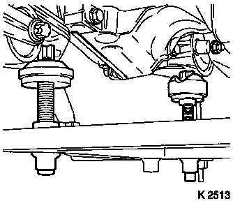
|
Important: When installing the
front axle body, ensure that the support bearings (1) of the KM-6169 are correctly seated in the guide pins
of the front engine damping block (2) and the rear engine damping
block bracket (3). If necessary, correct installation position of
engine and transmission using MKM-883-1
.
|
| 31. |
Install front axle body
|
|
|
| 32. |
Tighten 2 engine damping block brackets (1) at engine damping
block retaining bracket 80 Nm + 60°
– 75°
|
| 33. |
Detach and remove KM-883-1
|
|
|
| 34. |
Fasten transmission at the top
| • |
Tighten upper transmission bolts (arrows) 60 Nm
|
| • |
Tighten ground cable 60 Nm
|
| • |
Tighten wiring harness bracket 60
Nm
Note: If present.
|
| • |
Tighten coolant pipe bracket at transmission 60 Nm
Note: If present.
|
|
| 35. |
Connect wiring harness plug for coolant temperature sensor and
lock
Note: Only required for
Z 13 DT and Z 13 DTJ.
|
| 36. |
Attach pressure line (4) to connecting piece (2) for pressure
line for central release at clutch housing
Note: Clamp (3) must
audibly engage.
|
| 37. |
Connect wiring harness plug (1) to reversing lamp switch
|
|
|
| 38. |
Install charge air pipe (1)
Note: Only required for
Z 13 DT and Z 13 DTJ.
| • |
Clip in wiring harness (3)
|
|
|
|
| 39. |
Check transmission fluid level and correct if necessary
|
| 40. |
Slide shift guide onto shift rod
|
| 41. |
Transmission Shift Linkage, Adjust
|
| 42. |
Install lower and upper engine compartment cover
Note: If present.
|
| 43. |
Detach MKM-558-10 from brake fluid
reservoir
|
| 44. |
Install crash box
| • |
Z 13 DT / Z 13 DTJ / Z 17 DTH
|
|
| 45. |
Bleed hydraulic clutch actuation
| • |
Correct brake fluid reservoir to "MAX" mark
|
|
| 46. |
Program volatile memory
|
|
