|
Steering Gear, Replace
 Remove Remove
Warning: Before detaching the front
axle body, ensure that the engine damping blocks are correctly
fastened.
|
Important: Before removing the
steering intermediate shaft from the steering pinion or steering
shaft, put steering in straight-ahead position and lock with
steering lock.
|
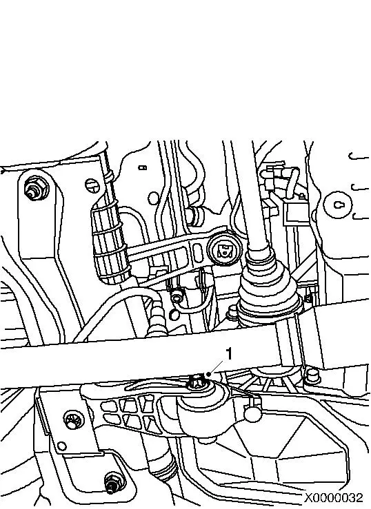
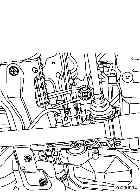
| 1. |
Remove lower clamp bolt (1) from steering intermediate shaft to
steering pinion
| • |
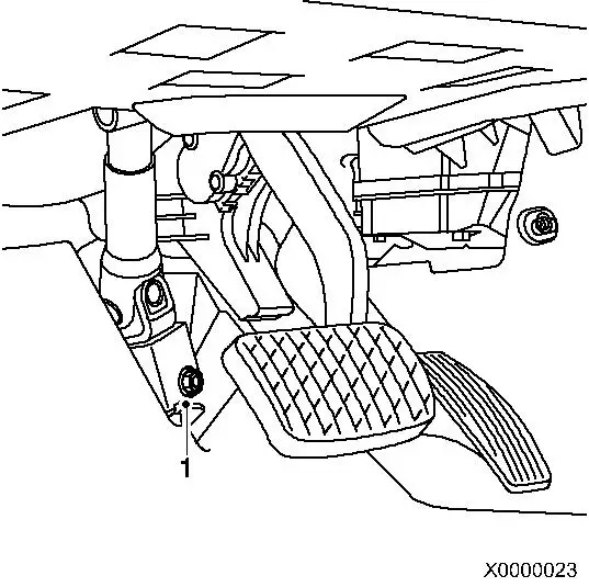
Remove steering intermediate shaft from steering pinion
|
|
|
|
| 2. |
Disconnect battery
Note: On vehicles with
ESP, the steering angle sensor will lose its basic setting after
the battery has been connected and will have to be
recalibrated.
| • |
Remove ground terminal from ground pole.
|
|
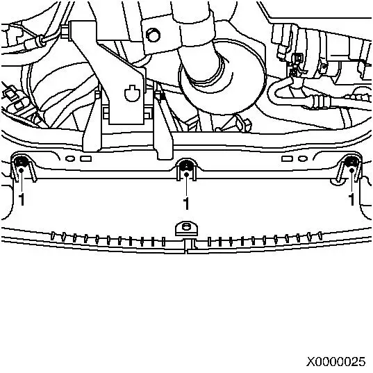
| 3. |
Secure cooling module
| • |
Fasten 2x tensioning straps (1) to the upper brackets
|
|
|
|
| 4. |
Release front panelling from front axle body
| • |
Detach 3x plastic rivets (1)
|
|
|
|
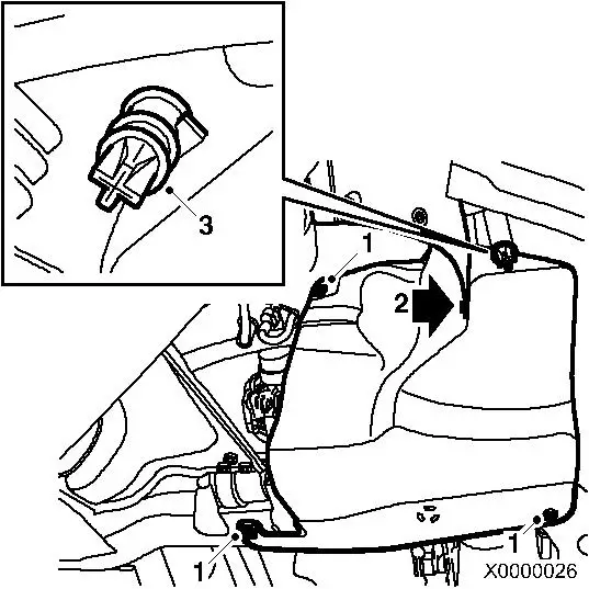
| 5. |
If fitted: detach right engine splash guard
| • |
Detach plastic rivet (2)
|
| • |
Unclip water drain hose (3)
|
|
|
|
| 6. |
For the Corsa-C ECO: detach lower engine compartment cover 
|
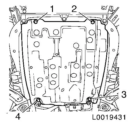
| 7. |
On the Combo-C with Bad Road Package: remove underbody
protection
| • |
Unscrew 2x bolts (1), (2)
|
| • |
Unscrew 2x nuts (4), (3)
|
|
|
|
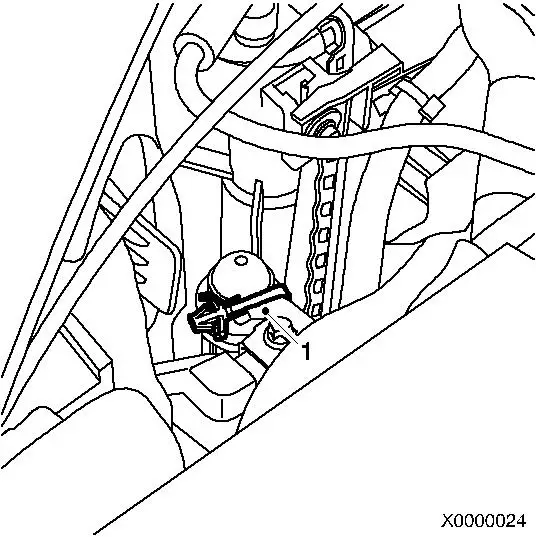
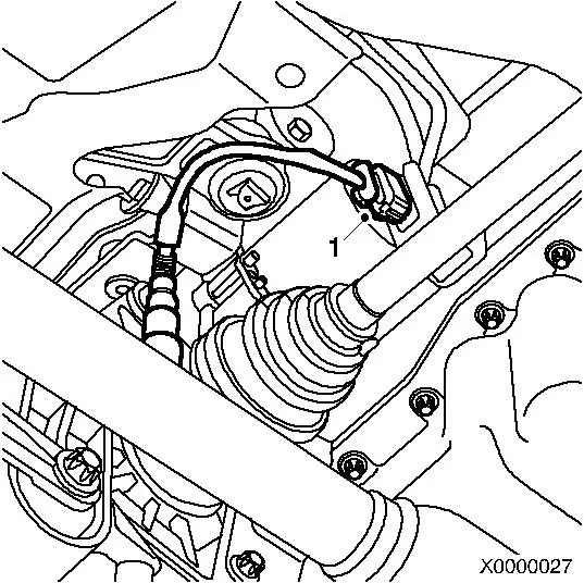
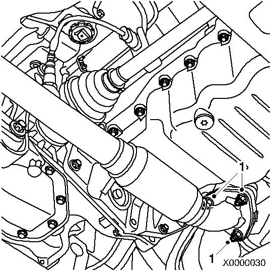
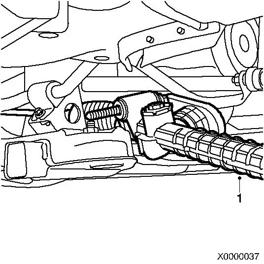
| 8. |
Petrol engine versions only: disconnect wiring harness plug (1)
of oxygen sensor
|
|
|
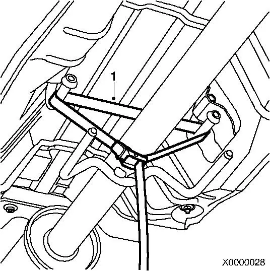
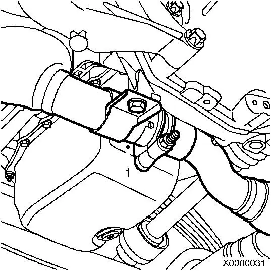
| 9. |
Release exhaust system
Note: On Z 16 YNG
engines, it is not necessary to secure the exhaust system.
| • |
Secure exhaust system to mount hooks with tensioning strap
(1)
|
|
|
|
| 10. |
For Z 16 YNG engines: disconnect 2x differential pressure
hoses
|
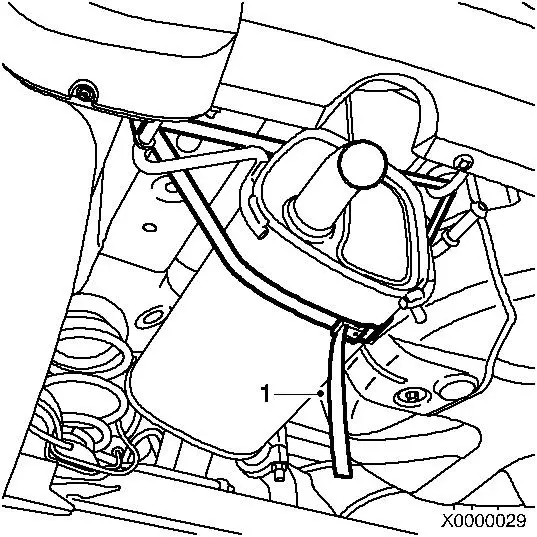
| 11. |
For Y 13 DT, Z 13 DT, Z 13 DTJ: also secure rear silencer
(1)
|
|
|
| 12. |
For Y 13 DT, Z 13 DT, Z 13 DTJ and Z 16 YNG engines: disconnect
plug connection (1)
|
|
|
| 13. |
All other engines: detach exhaust system from catalyst
|
|
|
| 14. |
Release rear reaction member
Note: For Y 17 DT, Y 17
DTL and Z 17 DTH, the entire rear reaction member must be removed.
See cross reference in step 13.
|
|
|
| 15. |
Remove rear reaction member
- Y 17 DT, Y 17 DTL
- Z 17 DTH
|
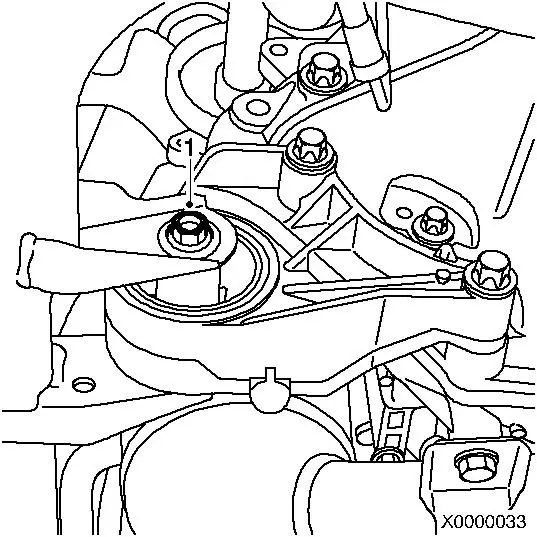
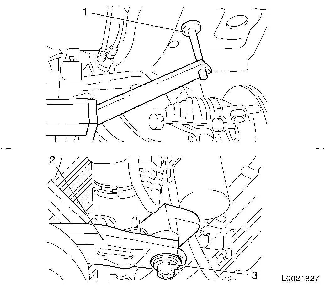
| 16. |
If fitted: detach front engine damping block
| • |
Unscrew bolt connection (1)
|
|
|
|
| 17. |
For vehicles with manual transmission: remove shift guide
strut
|
|
|
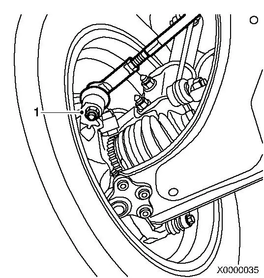
| 18. |
Detach 2x tie rod ends (1)
|
|
|
|
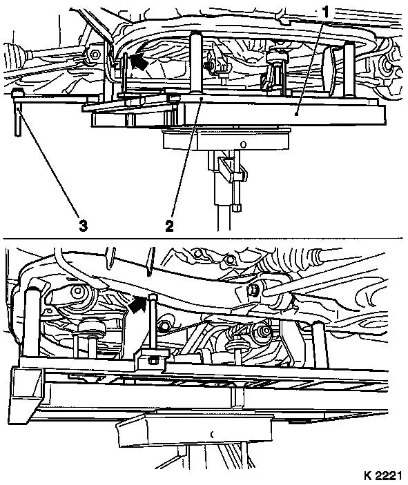
Important: Ensure that the guide
pins KM-6168-50 (arrows) are seated on
both sides in the guide holes of the front axle body.
|
| 19. |
Set up KM-904 (1) together with KM-6168 (2) on hydraulic jack and place under
front axle body with no play
Note: To remove the
front axle body, the positioning pins (3) on KM-6168-A (2) for the vehicle underbody must be
lowered in advance.
|
|
|
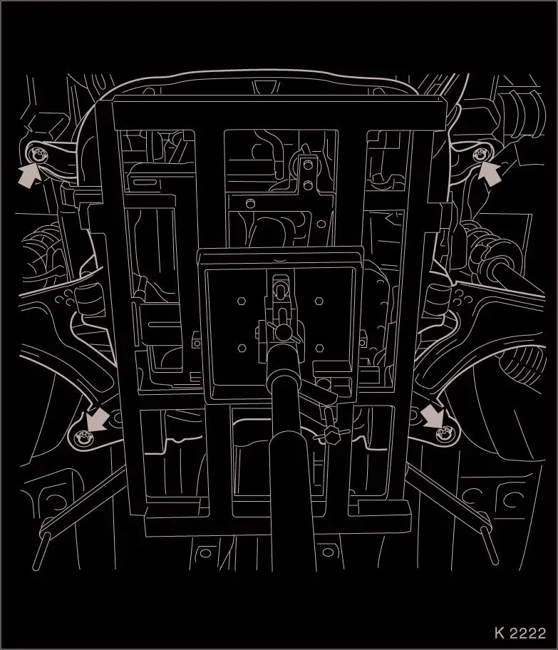
| 20. |
Detach front axle body
| • |
Unscrew 4x bolts (arrows)
|
| • |
Lower front axle body with hydraulic jack until the steering
pinion is sufficiently clear of the bulkhead
|
|
|
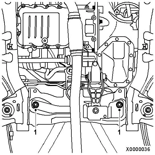
| 21. |
Remove steering gear from front axle body
| • |
Unscrew 2x bolt connections (1)
|
|
|
|
| 22. |
Remove steering gear (1) through right-hand wheel housing
|
|
|
 Install
| 23. |
When replacing the steering gear: transfer the tie rod ends
|
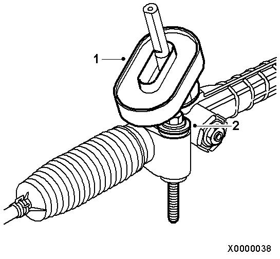
| 24. |
Move steering gear into installation position
Note: Attach gasket (1)
and 2x new bolts (2) to steering gear
|
|
|
| 25. |
Fasten steering gear to front axle body
Note: Use 2x new
washers
| • |
Tighten 2x new bolt connections (1) 45
Nm + 45° + 15°
|
|
|
|
|
Important: Ensure that the
radiator fixing pins (3) sit in the brackets (2) on the front axle
body and the positioning pins (1) of KM-6168-A engage in the positioning holes provided
for this purpose on the vehicle underbody.
|
| 26. |
Install front axle body
| • |
Move front axle body carefully with KM-6394 on KM-6168-A and
KM-904 with hydraulic jack onto vehicle
underbody, rear reaction member bracket and/or front reaction
member
|
| • |
Insert steering pinion of steering gear into bulkhead
penetration
|
|
|
|
| 27. |
Fasten front axle body
| • |
Tighten 4x new bolts (arrows) 90 Nm +
45° + 15°
|
|
| 28. |
For vehicles with manual transmission: attach shift guide
strut
|
|
| 29. |
Attach 2x tie rod ends
|
| 30. |
Attach rear reaction member
Note: For Y 17 DT, Y 17
DTL and Z 17 DTH, the entire rear reaction member must be
installed. See cross reference in step 29.
|
|
|
| 31. |
Install rear reaction member
- Y 17 DT, Y 17 DTL
- Z 17 DTH
|
| 32. |
If fitted: attach front engine damping block
|
|
|
| 33. |
For Y 13 DT, Z 13 DT, Z 13 DTJ and Z 16 YNG engines: connect
exhaust system plug connection to catalytic converter
|
|
|
| 34. |
All other engines: attach exhaust system to catalytic
converter
| • |
Tighten 3x new nuts (1) 25 Nm
|
|
|
|
| 35. |
For Z 16 YNG engines: connect 2x differential pressure
hoses
|
| 36. |
Petrol engine versions only: connect wiring harness plug of
oxygen sensor (1)
|
|
|
| 37. |
Fasten front panelling to front axle body
|
|
|
| 38. |
If fitted: attach right engine splash guard
| • |
Attach plastic rivet (2)
|
| • |
Clip in water drain hose (3)
|
|
|
|
| 39. |
For the Corsa-C ECO: attach lower engine compartment cover
|
| 40. |
On the Combo-C with Bad Road Package: attach underbody
protection
| • |
Clean 2x bolt threads
| – |
Insert 2x bolts with screw locking compound
|
|
|
| 41. |
Attach the steering intermediate shaft to the steering
pinion
Important: It must be possible to
push the universal joint easily by hand.
|
| • |
Tighten new bolt (1)
|
|
|
|
| 42. |
Adjust the straight-ahead position if necessary
|
| 43. |
Connect battery
| • |
Attach ground terminal to ground pole
|
|
| 44. |
Program volatile memories
|
|
