Corsa C
|
Headlamps, Exterior Lamps, Interior Lamps, Headlamp Switch, Check and Adjust
76/756 EEC or ECE-R48 guidelines cover checking and adjustment of headlamps on vehicle. Correct adjustment of headlamps on vehicle should enable optimal road illumination by low beam, with minimal dazzling of oncoming traffic. To this end, inclination of headlamp beam to level road surface and angle of beam to vertical longitudinal plane running through vehicle's centre must satisfy conditions laid down in guidelines. Dazzling (low beam) is considered eliminated if intensity of illumination at a distance of 25 m from each individual headlamp on the plane perpendicular to the road and at height of headlamp as well as beyond, is not greater than 1 lux. This requirement is generally satisfied if headlamp adjustment is carried out according to adjustment guidelines. Main headlamp housing or retainer displays reference 1.0 % for low beam adjustment according to EEC 76/756 or ECE-R48 guidelines. Reference 1.0 % corresponds to the adjustment dimension of the headlamp with reference to the inclination of the light beam. The inclination at a distance of 10 m from vehicle headlamp is therefore 10 cm (illustrations L 0017601 and L 0017602). The inclination of the dipped beam headlamp is indicated by its light/dark boundary.
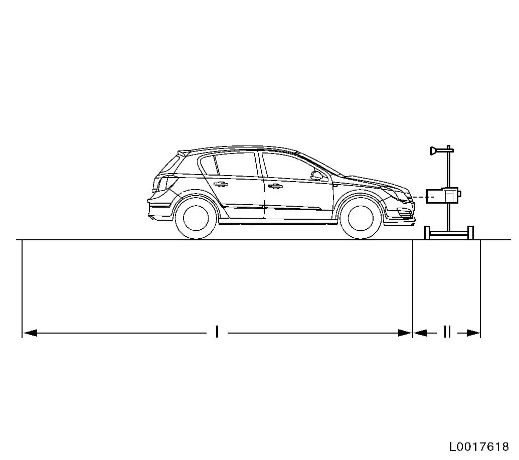
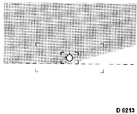
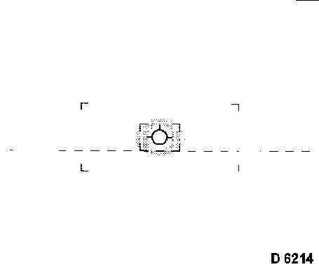
The headlamp adjustment is performed according to the specifications, as shown in Illustration D 6213 and D 6214, using an adjuster. When using a headlamp adjuster, ensure that vehicle tyre area in contact with the road and the surface for setting up the adjuster are level and parallel with one another.
Vehicle tyres must have specified air pressure. Defective headlamp lenses and mirrors as well as blackened bulbs must be replaced before adjusting. The adjustment is performed at vehicle curb weight plus one person or 75 kg on the driver's seat. (Curb weight = weight of vehicle ready for use with completely filled fuel tank plus the weight of all equipment carried during use, e.g. spare wheel, tools, jack, first aid kit, emergency warning triangle, etc.). Vehicles with manual level control must be adjusted to the specified basic pressure ( 0.8 bar at curb weight). If manual headlamp range control is fitted, switch the ignition on and position the adjuster wheel of the light switch centre to "0". The intersection between the horizontal and the ascending parts of the light/dark boundary (break point) must lie on the perpendicular through the central marking. For easier determination of the intersection point, headlamp halves can be alternately covered and uncovered. The headlamp adjusting equipment used must comply with the existing guidelines and the manufacturer's operating instructions must be observed. The headlamp adjuster must be regularly checked by manufacturer's maintenance service.
|
||||||||||||||||||||||||||||||||||||