|
Damage diagnosis, dual mass flywheel
In normal driving mode, the friction of the clutch plate on the
friction surface of the dual mass flywheel causes temperatures of
up to 200 °C. If the clutch is slipping or in the case of
incorrect operation, far higher temperatures can occur which
however do not necessarily lead to a reduction in the life of the
dual mass flywheel.
Possible signs of high thermal load are:
- Run-up colour (blue-ish) and local heat flecks (hot spots) on
the friction surface
- Run-up colour (blue-ish) in the area of the clutch screw
surface and in the rivet area
If all other aspects which can be checked are OK, the dual mass
flywheel can remain in the vehicle.
Possible signs of excessive thermal load are:
- Cracks
- Melted deposits on the friction surface (smeared material)
- Grooves in the friction surface (e.g. from clutch lining rivets
when the clutch plate is damaged or worn)
- Run-up colour (blue-ish) which extends into the bearing zone of
the dual mass flywheel
- Coloured (blue-ish) discoloration of the aligning pins (3
aligning pins in the outer area of the dual mass flywheel)
In these cases, the dual mass flywheel must be replaced.
|
|
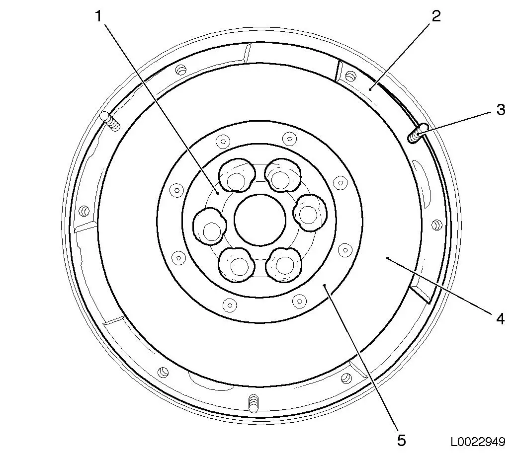
Overview dual mass flywheel
| 1. |
Bearing zone |
| 2. |
Screw surface for thrust plate |
| 3. |
Alignment pins |
| 4. |
Friction surface |
| 5. |
Riveting area |
|
|
|
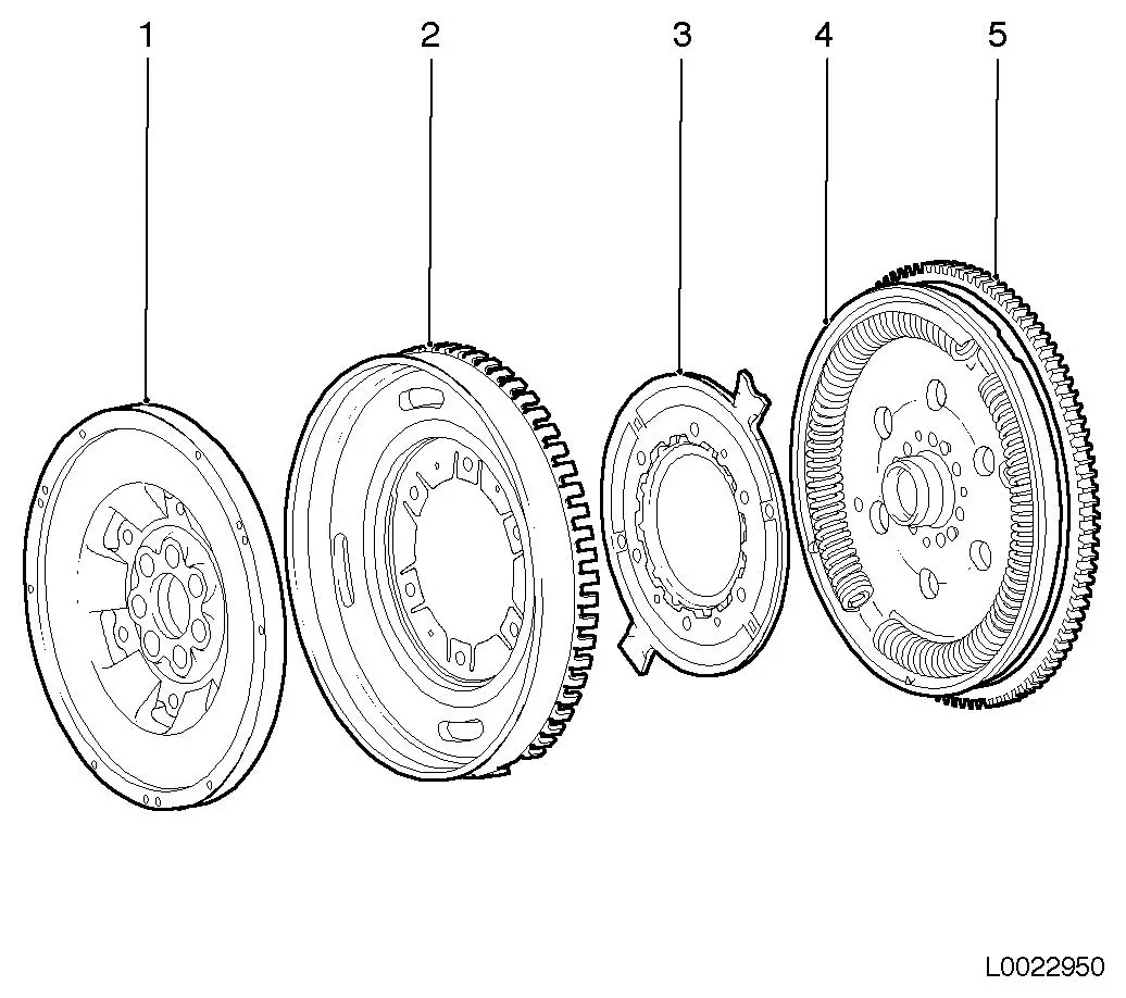
Exploded view of dual mass flywheel with extra
mass
| 1. |
Secondary centrifugal mass |
| 2. |
Extra mass connected to cover and transfer
ring |
| 3. |
Flange |
| 4. |
Primary centrifugal mass with base springs and
plain bearings / bearing mandrel |
| 5. |
Crown gear |
|
Visual inspection for damaged components
Important: All
visual inspections below are carried out with the dual mass
flywheel installed.
For a visual inspection in the vehicle, very bright light and
also a bright narrow beam torch are required. Damage signs such as
traces of grease on the primary flywheel and loose or missing
balancer weights cannot be checked with the unit installed.
On visual inspection, material changes can be established which
may exclude further use of the dual mass flywheel. For comparison,
various damage pictures are presented here for the dual mass
flywheel with corresponding further procedures.
|
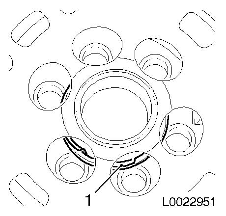
Check plain bearings for damage
On mechanical damage to the plain bearings, the dual mass
flywheel must be replaced.
The damage can be identified, depending on manufacturer, through
the ventilation windows in the secondary flywheel. Parts of the
bearing (1) have become detached or lie loosely around the bearing
mandrel.
Note: On mechanical
damage to the plain bearings, the dual mass flywheel must be
replaced.
|
|
|
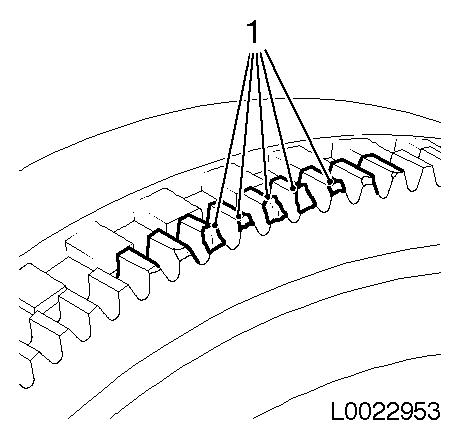
Check crown gear for damage
The crown gear is required to start the engine. Repeated start
procedures and/or an incorrectly engaging starter can cause wear
phenomena on the teeth of the crown gear. The damage profile can
range from slight traces of wear through to severe abrasion.
Installation of a transfer ring is model-dependent.
Graphic L:0022953 shows traces of abrasion and mechanical damage
to the crown gear (1). This is the result of wear due to many
starting processes. In this case, the dual mass flywheel must be
replaced.
Note: Slight wear on
the face of the teeth is acceptable. If problems occur on starting
the engine however, the dual mass flywheel must be changed.
|
|
|
|
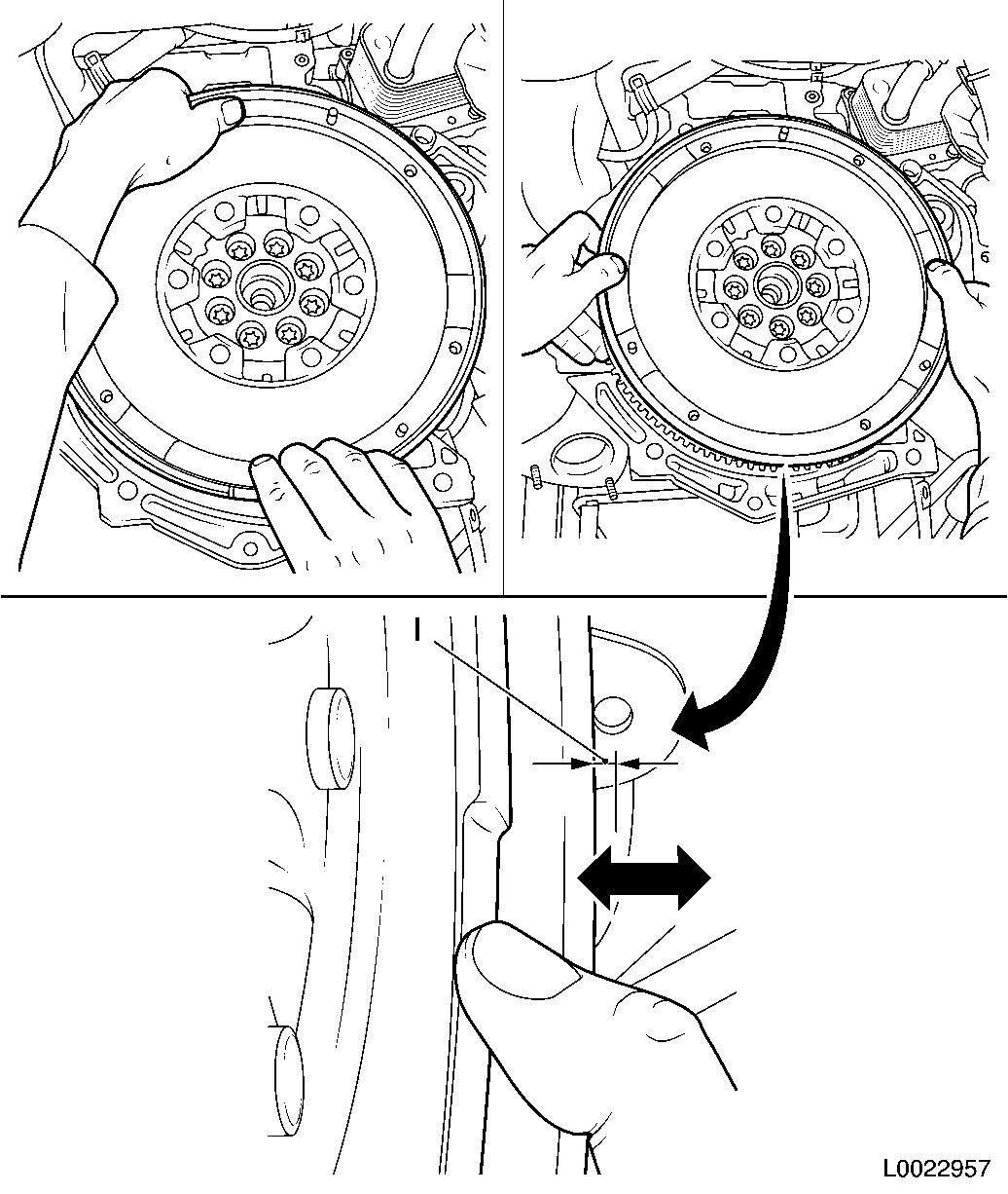
Check tilt play.
In the dual mass flywheel, the extra mass ring projects over the
gap between the primary and secondary centrifugal masses. A simple
visual inspection of the tilt play is not possible.
1. Grip the dual mass flywheel and place thumbs on the outer
radius of the secondary flywheel.
2. With your thumbs, press on the secondary flywheel (arrows)
alternately first at the top, then at the bottom, then on the left
and then on the right sides.
When checking the tilt play, metallic rattling noises can occur
because of the function.
Note: The test may
only be performed by hand without using tools.
If the tilt play is greater than 3
mm (l) (measured, not a subjective assessment), the dual
mass flywheel must be changed.
It is not possible to carry out an absolutely clear measurement
with this test as the conditions are not standardised due to the
differences in force exerted by individual workshop staff during
the test.
|
|
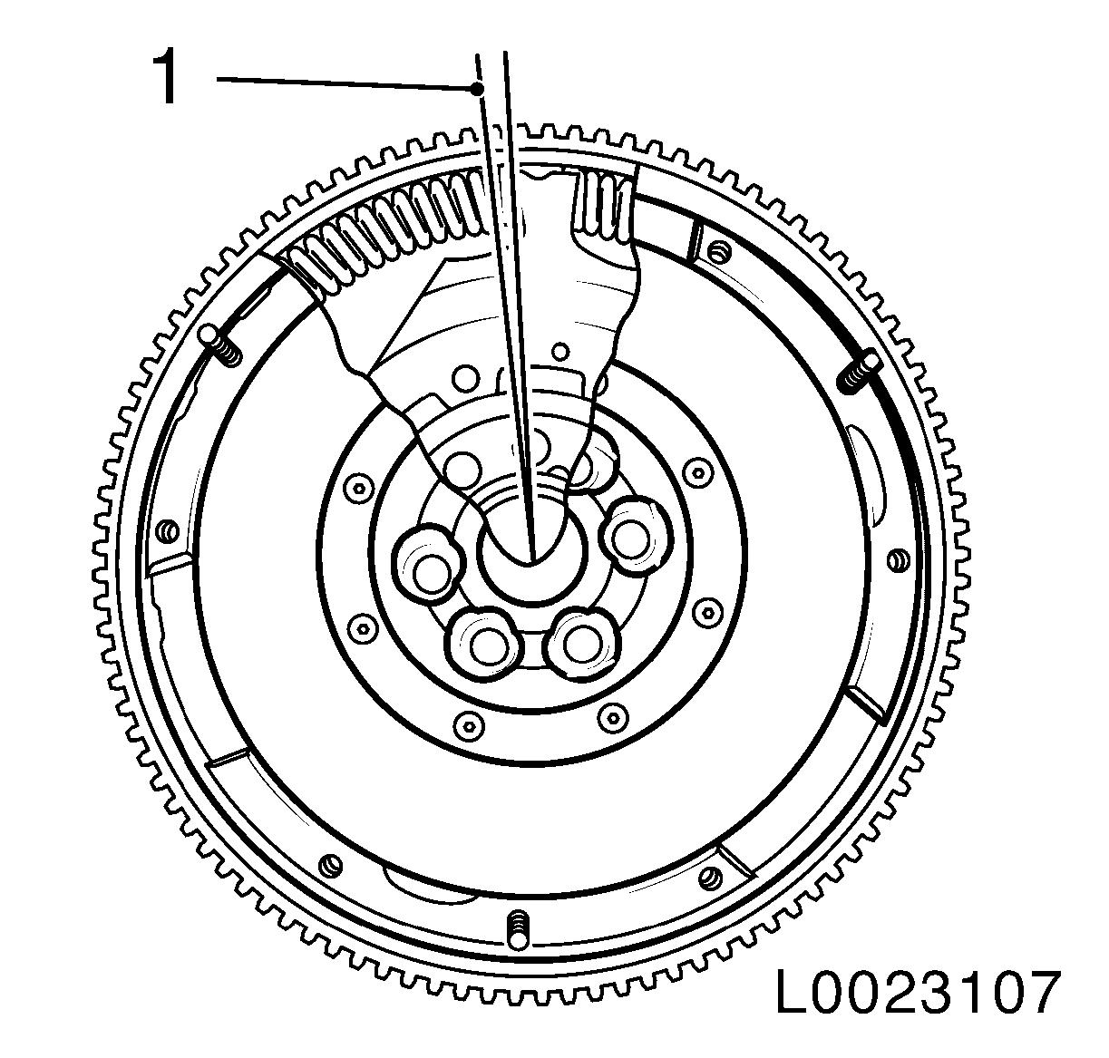
Check clearance angle
Before checking the clearance angle, slowly turn the dual mass
flywheel clockwise and counterclockwise to get a feel for the
resistance of the springs. In addition, unusually loud cracking
noises may be heard, together with possible rattles, clattering or
grinding when turning the dual mass flywheel. If the dual mass
flywheel cannot be turned, it is faulty and must be replaced.
The clearance angle is the angle (1) through which the secondary
and primary flywheels can be twisted freely against each other. The
flange wing in the base spring channel moves without contacting the
base spring. The clearance angle is up to 8 teeth depending on
function.
If the secondary flywheel is turned beyond this point, the base
springs will be pushed into the channel up to the base spring stop
in the primary flywheel/cover. Only now is the spring force of the
base springs exerted.
|
|
|
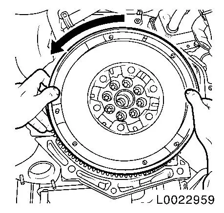
1. Twist secondary flywheel counterclockwise (arrow) until the
elastic counter-force (spring force) of the base springs can be
clearly felt.
2. Slowly release the secondary flywheel until the base springs
are relaxed, i.e. until there is no more counter-force on the
springs.
|
|
|
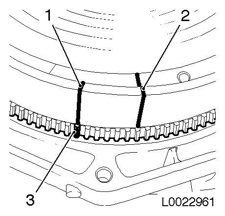
3. Mark position clearly with a vertical line in white pen on
the secondary flywheel (1) and on the starter crown gear (2).
4. Turn secondary flywheel far enough clockwise until the
elastic counter-force can be clearly felt again.
5. Slowly release secondary flywheel until the base springs are
relaxed.
|

|
|
6. Make a new mark (1) on the secondary flywheel at the level of
the first mark on the starter crown gear (3).
7. Count the number of teeth on the starter crown gear from the
tooth marked to the first mark on the secondary flywheel (2). Up to
8 teeth difference is permitted depending on function.
Note: Replace the
secondary flywheel if:
- the difference is more than 8 teeth
- the dual mass flywheel cannot be turned
- when turning the dual mass flywheel, a hard metallic stop can
be heard or felt.
|
|
|
