|
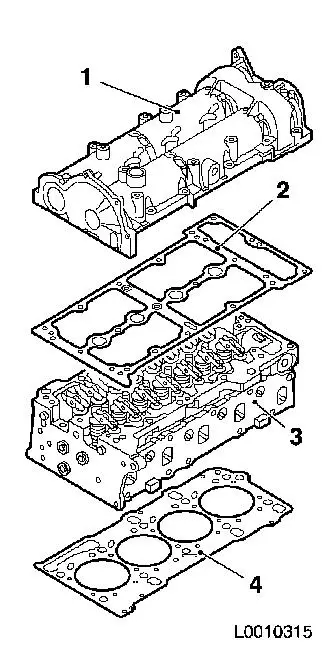
Seal camshaft housing to cylinder head
Warning: When
working on the Common Rail system, wait for one minute after
switching off the engine. The system reduces the pressure
automatically.
Important: When
working on the fuel system, pay strict attention to cleanliness as
even the smallest particle of dirt may lead to malfunctions in
engine operation or the fuel system. Seal opened fuel connections
with suitable sealing plugs1. Sealing plugs are intended for single
use.
 Remove Remove
| 2. |
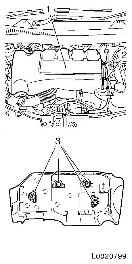
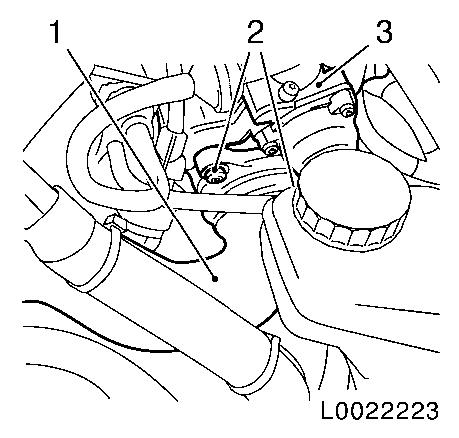
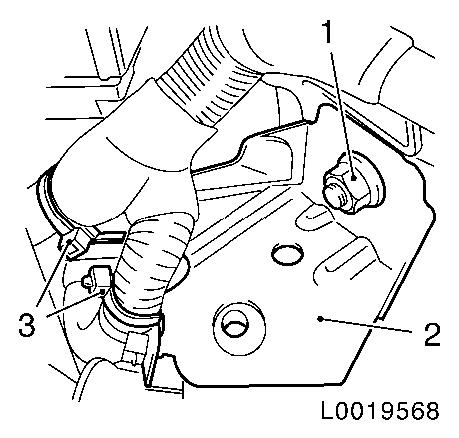
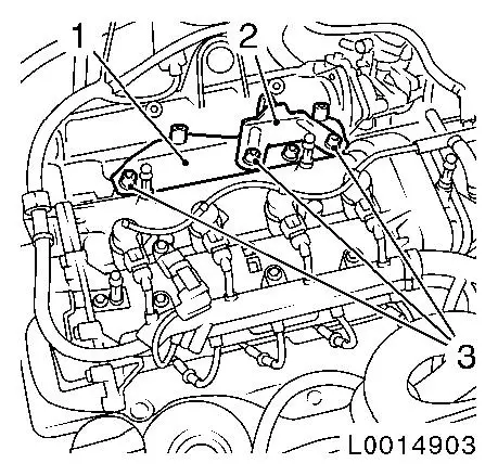
Remove engine cover (1)
| • |
Pull off engine cover
Note: Rubber retainers
(3) must remain on engine cover.
| – |
Unclip coolant return hose from bracket
|
| – |
Unclip vacuum line (2) from bracket
|
|
|
|
|
| 3. |
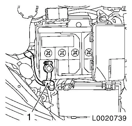
Disconnect battery
| • |
Detach ground connection (1) from ground terminal
|
|
|
|
| 5. |
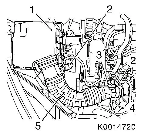
Remove air cleaner housing (1) with air intake hose (5)
| • |
Disconnect 2x wiring harness plugs (2)
|
| • |
Remove air intake hose from turbocharger
|
| • |
Detach oil separator hose from air intake hose
|
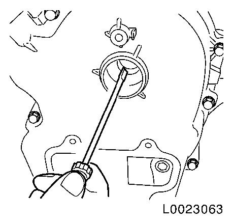
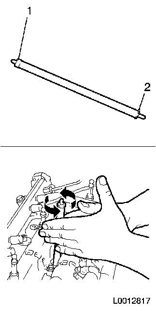
| • |
Detach water drain hose from lower part of air cleaner
housing
| – |
Pull off hose from air cleaner housing
|
|
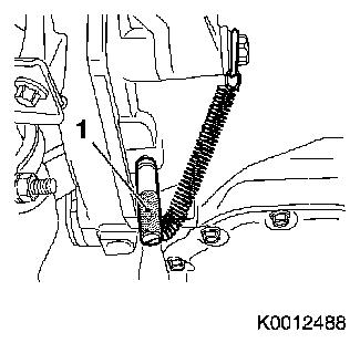
| • |
Detach air cleaner housing from wheel housing
| – |
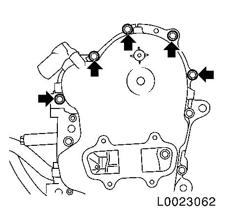
Press out from rubber retainer in 3 places
|
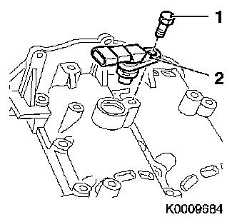
|
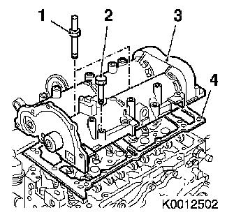
|
|
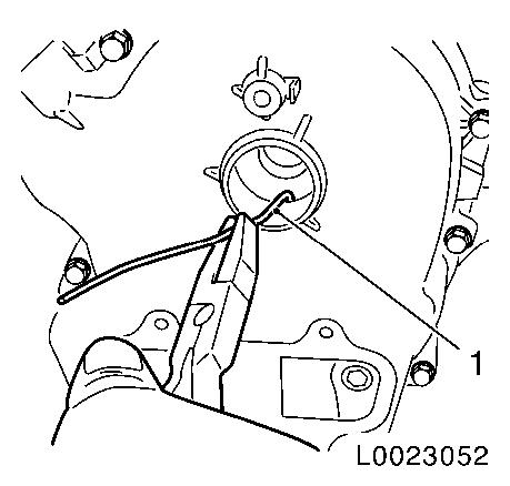
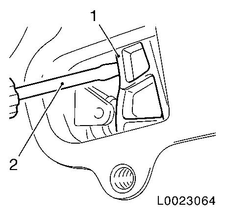
|
| 6. |
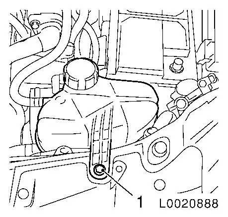
Remove coolant expansion tank
|
|
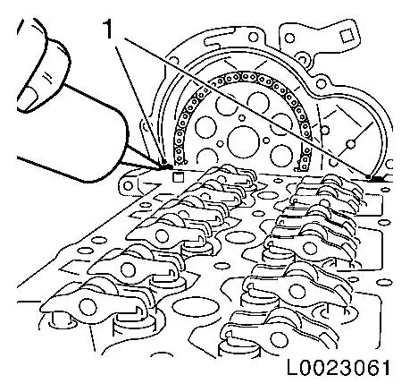
|
| 7. |
Remove brake force amplifier vacuum line
|
| 8. |
Detach charge air pipe (1) from throttle valve module (3)
| • |
Detach charge air pipe from transmission bracket
|
|
|
|
| 9. |
Disconnect wiring harness connector (black) from glow-control
unit
|
| 10. |
Remove mixture regulation oxygen sensor 
|
| 11. |
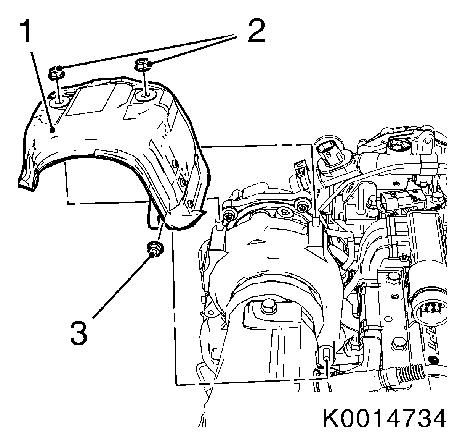
Detach turbocharger heat shield (1)
|
|
|
| 12. |
Detach engine vent hose
| • |
Disconnect wiring harness connector.
|
| • |
Separate plug connection
|
|
| 13. |
Remove dipstick guide tube
|
| 14. |
Remove 2x fuel line
| • |
Seal connections with KM-807 or KM-6015
|
|
| 15. |
Expose engine management wiring harness
| • |
Remove 18x wiring harness plug
| – |
Camshaft sensor, wastegate unit, high-pressure pump, oil
pressure switch, crankshaft sensor, 4x glow plugs, 4x injectors,
throttle valve module, coolant temperature sensor, charge air
sensor, rail pressure sensor, differential pressure sensor
|
|
|
| 16. |
Detach 2x wiring harness brackets from camshaft housing
|
| 17. |
Detach wiring harness from intake manifold
| • |
Detach differential pressure pipe bracket
|
|
| 19. |
Detach oil filler port from timing case
|
| 20. |
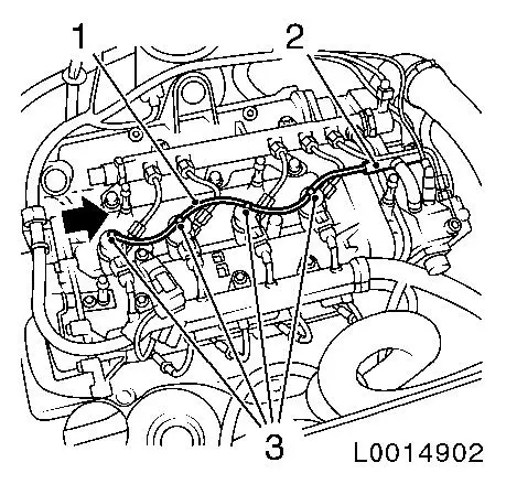
Remove oil leak line (1)
| • |
Detach from fuel return pipe (2)
|
| • |
Unlock 4x retaining clamps (3) in direction of arrow
|
|
|
|
Important: Counterhold bolt at
high pressure pump with open-ended wrench
|
| 21. |
Remove high pressure line of high pressure pump (3) from
accumulator (1)
|
Important: Counterhold bolt at
injector with open-ended wrench.
|
| 22. |
Detach 4 high pressure lines from accumulator to injector
(4)
|
|

|
| 25. |
Raise vehicle by half its height
|
| 26. |
Detach 2x front wheels
|
| 27. |
Remove engine splash guard
|
| 28. |
Remove 2x front wheelhouse front liner
|
| 30. |
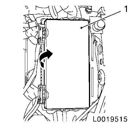
Remove engine compartment electronics module (1)
| • |
Rotate the fuse box clockwise and release
|
| • |
Release left headlamp wiring harness plug and pull it off
|
| • |
Free the wiring harness in the vicinity of the left
headlamp
|
|
|
|
| 31. |
Detach wiring harness bracket (2)
| • |
Unclip 2 wiring harnesses (3)
|
|
|
|
|
| 32. |
Use CH-48373-3 (left-hand)
| • |
Unfold support (1)
Note: Use a second
person to hold the engine compartment electronics module
|
|
|
| 33. |
Attach support frame and engine bridge
|
| 34. |
Secure the engine
| • |
Attach 2x hooks to engine transport shackle
|
|
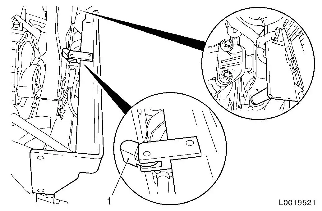
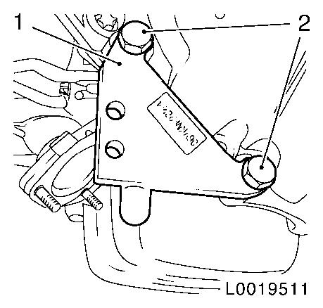
| 35. |
Detach right engine damping block
| • |
Unscrew 3 side member bolts (1)
|
| • |
Unscrew 3 bolts (2) from the engine damping block support
|
|
|
|
| 36. |
Screw 3x bolts of engine damping block into side member
Note: Use suitable
washers under the bolts to even up height of engine damping
block
|
|
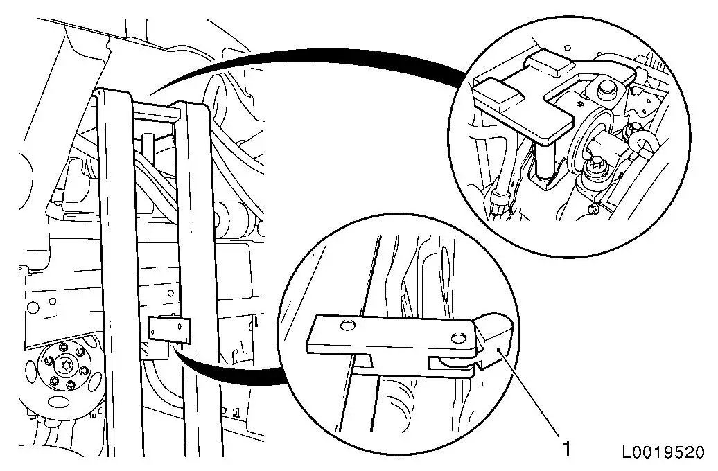
| 37. |
Insert CH-48373-2 (right-hand) from
above
|
|
| 38. |
Raise vehicle by its full height
|
| 39. |
Attach CH-48373-7 (1) to
transmission
|
|
|
|
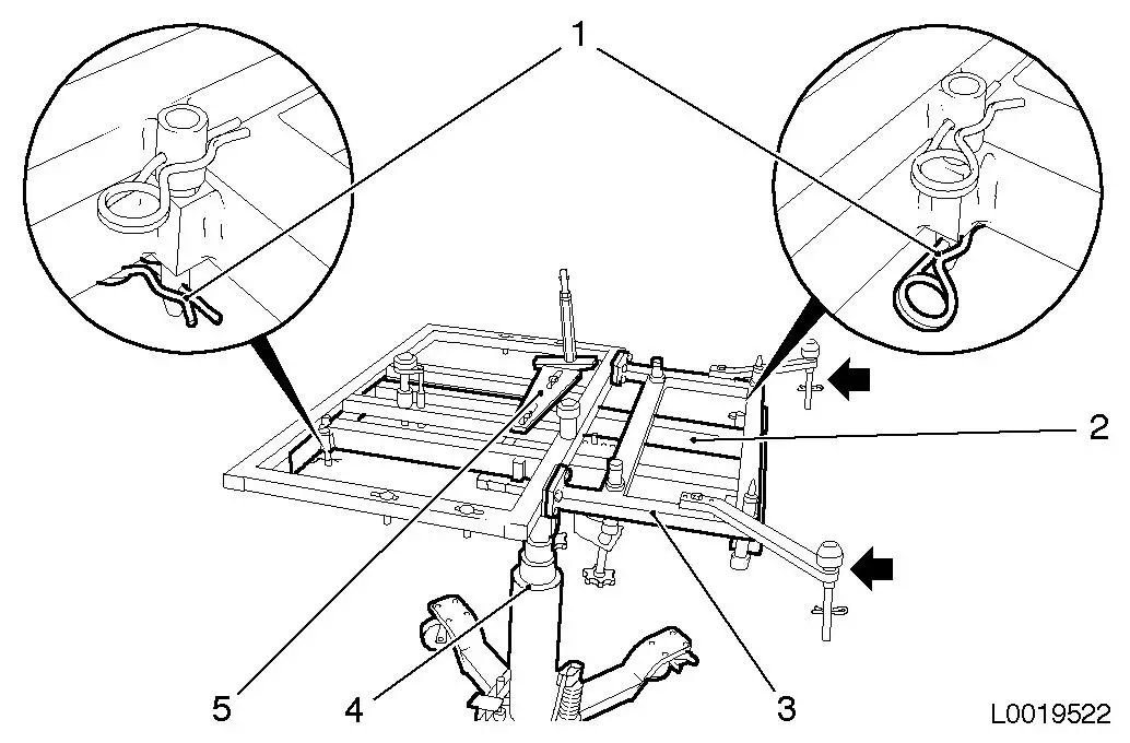
| 40. |
Place KM-904 (2) and CH-48373-1 with CH-48373-12
(3) on hydraulic jack (4)
| • |
Attach 2x retaining pins
|
| • |
Attach 2x cotter pins (1)
|
| • |
Place probes (arrows) downward
|
|
|
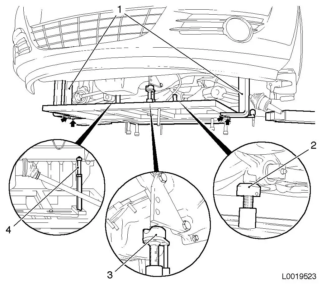
| 41. |
Support engine and transmission with hydraulic jack
| • |
Connect CH-48373-2 (1) and CH-48373-3 (1) to CH-48373-1
|
| • |
Tighten 4 bolted connections
|
| • |
Screw support (2) up until it is pressing gently against the
rear reaction member bracket
|
| • |
Screw support (3) up until it is pressing gently against CH-48373-7
|
| • |
Screw support (4) up until it is seated under gentle pressure
in the hole provided for it in the cylinder block
|
|
|
|
| 42. |
Extend the hydraulic jack
|
| 43. |
Lower vehicle by its full height
|
| 44. |
Remove the engine bridge and support frame
|
| 45. |
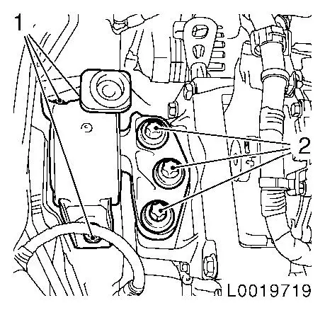
Remove engine damping block adapter (1)
|
|
|
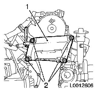
| 46. |
Remove pressure reservoir bracket (1) with engine transport
shackle (2)
|
|
|
|
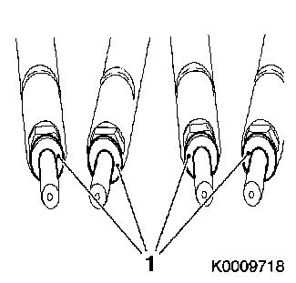
| 47. |
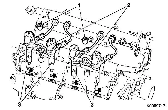
Remove 4x injector (3)
| • |
Remove 2x injector bracket (2)
|
| • |
Remove 4x seal ring (arrows)
|
| • |
Seal 4x injector with protective cap
Note: If the injectors
cannot be removed manually, use EN-46786
connected to KM-328-B .
|
|
|
| 48. |
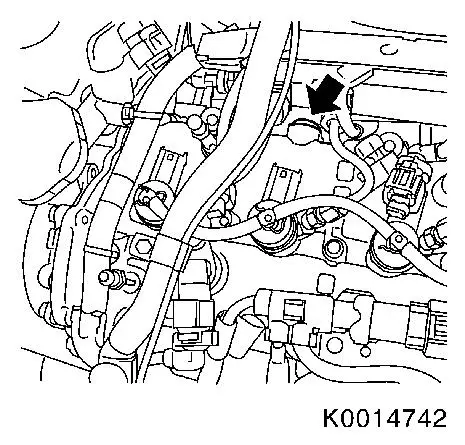
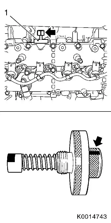
Remove closure bolt (arrow) from intake side of camshaft
housing
|
|
|
| 49. |
Disconnect intake camshaft
Note: Apply guidance
marking on reference drift (arrow).
| • |
Screw in camshaft reference drift EN-46781 (1)
|
| • |
Ensure correct installation position
Note: Reference drift
fixing must be installed in a horizontal position.
|
|
|
|
| 50. |
Lock intake camshaft
| • |
Turn crankshaft in direction of engine rotation until EN-46781 engages in camshaft
|
|
| 51. |
Lock crankshaft
| • |
Insert EN-46785 (1) through hole in
transmission bell housing
|
| • |
Carefully turn crankshaft bolt until EN-46785 engages in flywheel
|
|
|
|
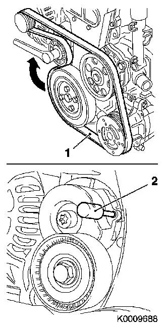
| 52. |
Remove ribbed V-belt (1)
| • |
Mark direction of rotation
|
| • |
Apply tension clockwise to tensioner at tension roller bolt
(arrow)
|
| • |
Lock tensioner with KM-6130 (2)
Note: The ribbed V-belt
must be removed to prevent contamination.
|
|
|
|
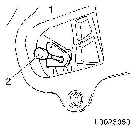
| 53. |
Remove closure bolt (1) from timing case
|
| 54. |
Remove chain tensioner closure cap (2)
| • |
Unscrew 4x screw (arrows)
Note: Reuse
gaskets.
|
|
|
|
| 55. |
Undo bolt of exhaust camshaft drive gear
Note: Do not remove the
bolt yet.
|
| 56. |
Tension timing chain tensioner
| • |
Apply tension to chain tensioner (1) using a suitable tool,
lock in pre-tensioned position KM-955-1
(2)
|
|
|
|
| 57. |
Detach exhaust camshaft drive gear
| • |
Unscrew fastening bolt
Note: Bolt is to be
re-used.
|
| • |
Using a bent piece of rigid wire (1), pull drive gear from
exhaust camshaft
|
|
|
|
| 58. |
Release timing case top from camshaft housing
| • |
Unscrew 5x bolts (arrows)
|
|
| 59. |
Detach engine cover bracket
|
|
|
| 60. |
Remove camshaft sensor (2)
|
|
|
| 61. |
Release camshaft housing (3)
| • |
Unscrew 16x bolt (2)
Note: Note different
bolt lengths.
|
| • |
Unscrew 2x threaded pin (1)
|
|
|
|
| 62. |
Remove camshaft housing
| • |
Carefully slide camshaft housing from timing case and remove
it.
Note: Carefully lever
camshaft housing off timing case gasket with plastic wedge and use
a rubber mallet to knock it off the timing case. Place camshaft
housing on suitable support
|
|
 Install
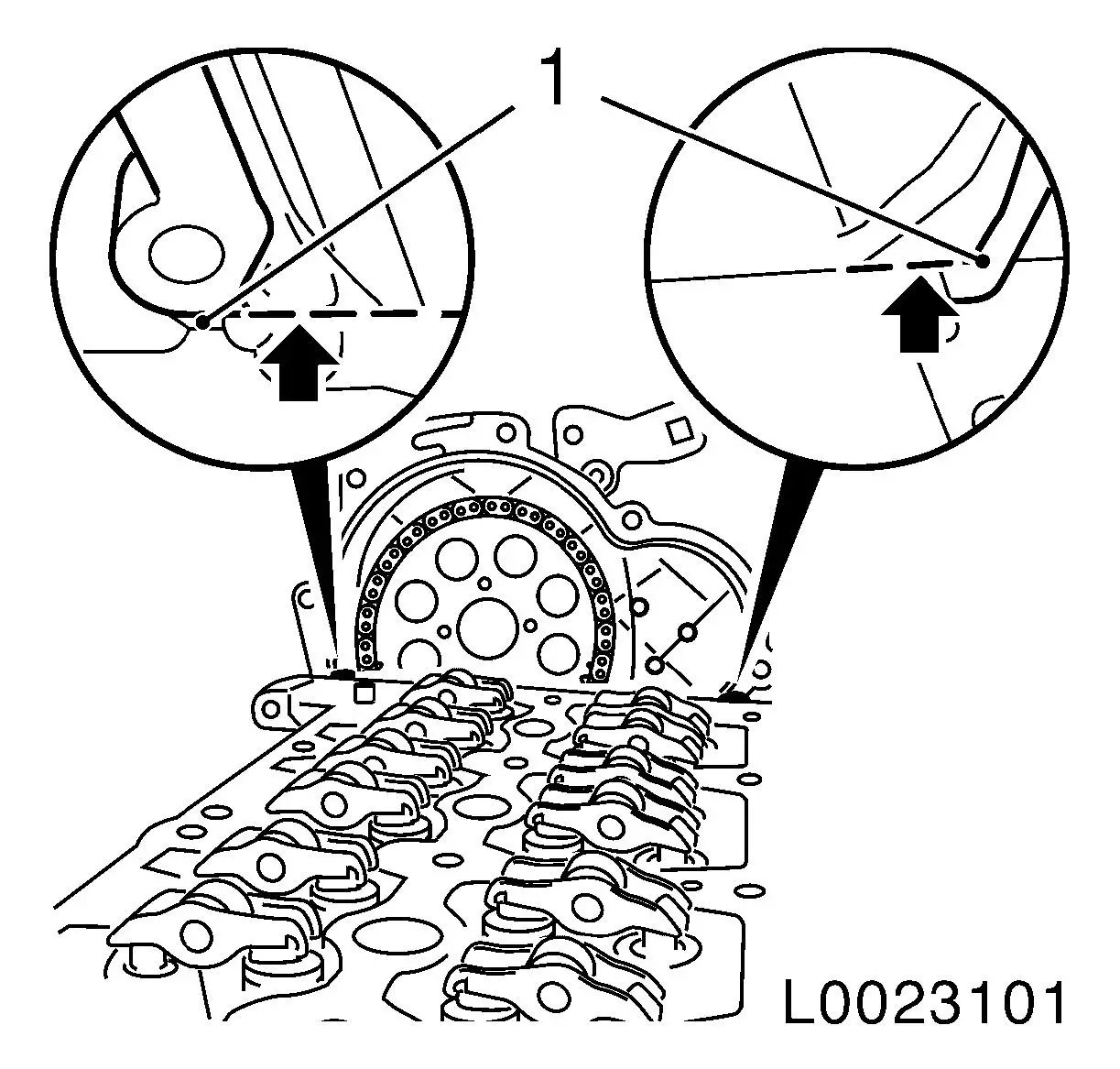
| 63. |
Remove timing case gasket
| • |
Cut into the elastomer sealing lips (arrows) using a sharp
knife pressed against the cylinder head,
|
| • |
With a plastic spatula, loosen the seal from the timing case
and carefully snap it off at the designated point (1)
|
| • |
Remove any gasket residue and clean all sealing surfaces
thoroughly
Note: Make sure that no
residues remain at the joint between the timing case and cylinder
head, and that no bits of the gasket fall into the timing case.
|
|
|
|
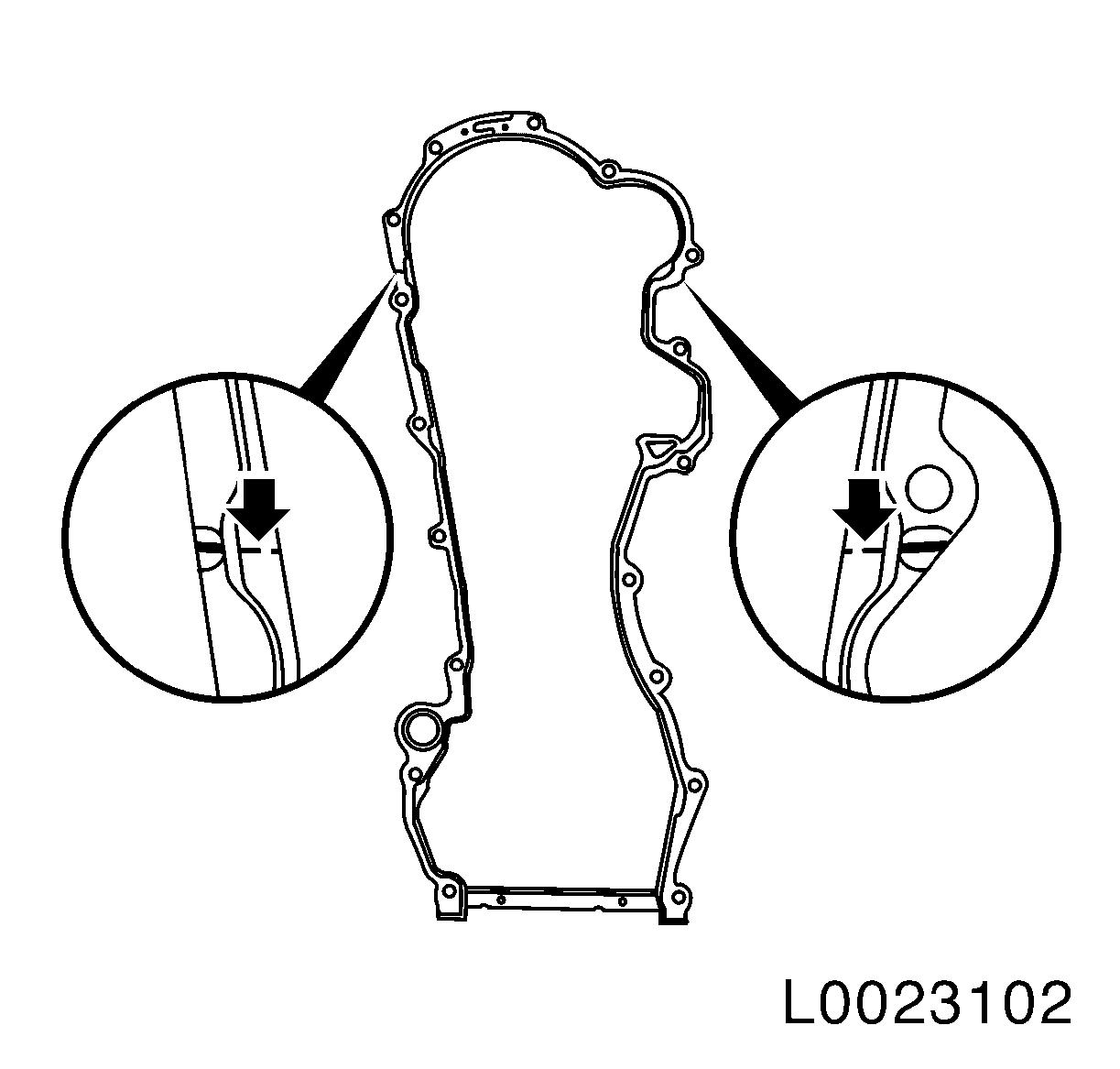
| 64. |
Fit timing case gasket
| • |
Using a sharp knife, cut into the elastomer sealing lips
(arrows) at the breaking points of the new gasket
|
|
|
|
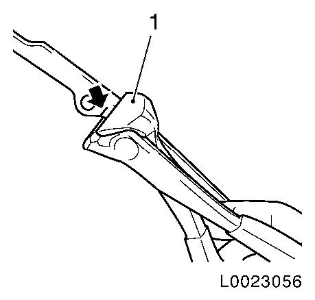
| 65. |
Cut the new timing case gasket off at the lower breaking
points
| • |
Using pincers (1), cut the seal at both breaking points
(arrow)
Note: It is essential
for the cutting tool to have a straight cutting surface.
|
|
|
|
Important: The upper new gasket
and the old lower gasket must not be allowed to overlap.
|
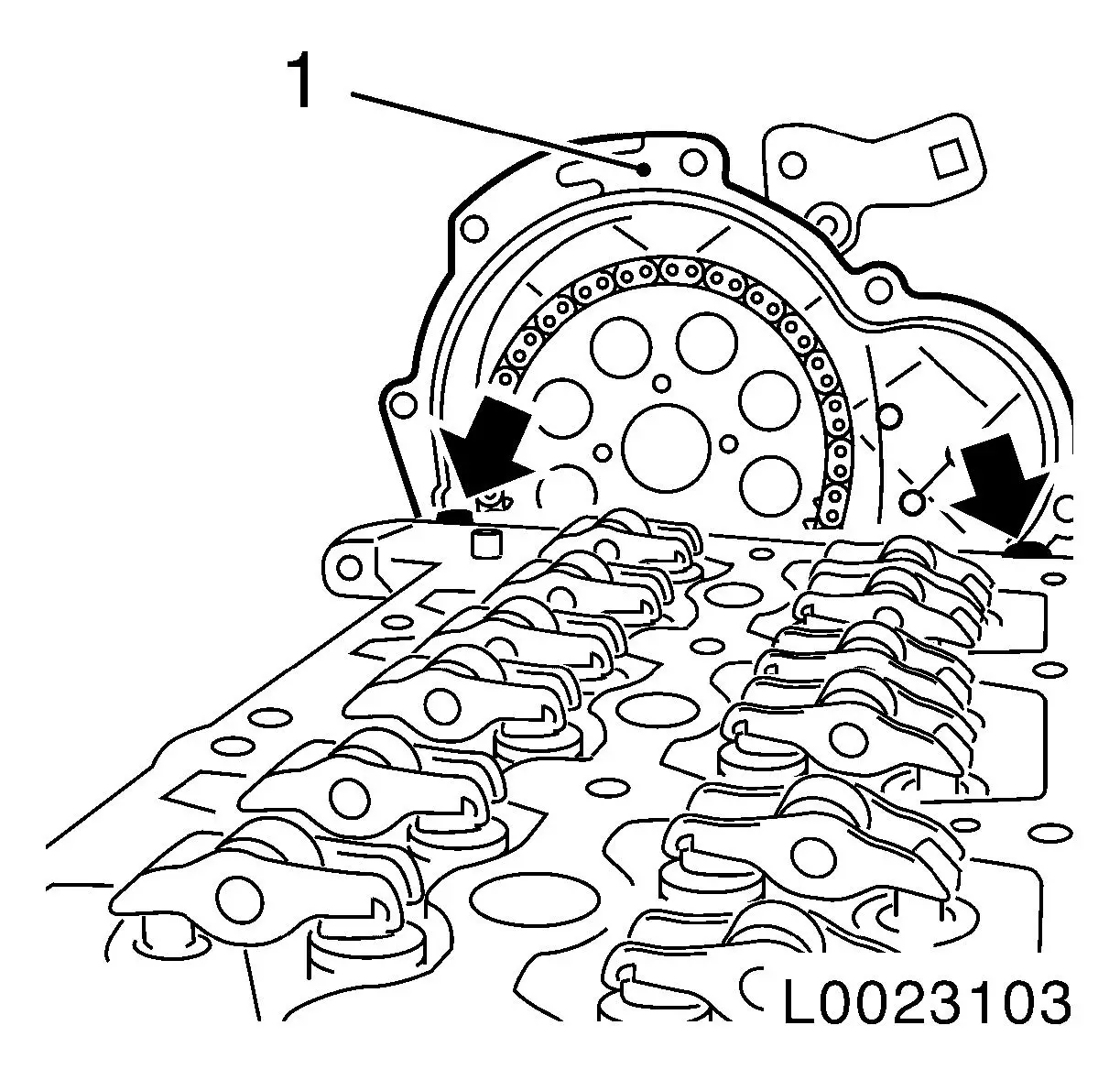
| 66. |
Fit new timing case gasket
| • |
Using the pincers, fit the new gasket (1) to the contact
surface between the cylinder block and the timing case until the
seal lies flush on the cylinder head and timing case (arrows) and
the holes in the gasket and the timing case match up.
|
|
|
|
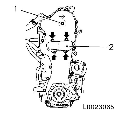
| 67. |
Clean contact surfaces
| • |
Clean any oil and grease off the exhaust camshaft, drive gear,
bolt and thread in exhaust camshaft
|
|
| 68. |
Attach new camshaft housing gasket
| • |
Clean all sealing surfaces
|
| • |
Apply sealant to contact surfaces (1) of cylinder head and
timing case
|
| • |
Place gasket on camshaft housing
|
|
|
|
|
| 69. |
Install camshaft housing
| • |
Remove 2x fastening bolts and nuts from timing case gasket
|
| • |
Position camshaft housing
|
| • |
Screw in 16x bolts according to tightening sequence until the
camshaft housing is lying evenly on the cylinder head, but do not
tighten them yet
Note: Note longer bolt
(14)
|
|
|
| 70. |
Fasten timing case to camshaft housing
| • |
Carefully align the camshaft housing on the timing case, using
the rubber mallet.
|
| • |
Screw in 5x bolt (arrows) until the camshaft housing is in
contact with the timing case
|
|
|
|
|
| 71. |
Fasten the crankshaft housing
| • |
Tighten 16x bolt, observing the correct tightening sequence
18 Nm
|
| • |
Tighten 2x stud bolt 25 Nm
|
|
|
| 72. |
Tighten all bolts holding timing case to camshaft housing
|
|
|
Important: The exhaust camshaft,
drive gear, bolt and thread in exhaust camshaft must be free of oil
and grease.
|
| 73. |
Place drive gear on exhaust camshaft
| • |
Position drive gear on exhaust camshaft using a suitable
tool
|
| • |
Screw in bolt
Note: Don not tighten
yet!
|
|
|
|
| 74. |
Tension timing chain tensioner
| • |
Release the timing chain tensioner, using a suitable tool
|
|
| 75. |
Fasten the exhaust camshaft drive gear
| • |
Tighten bolt 150 Nm
Note: A second mechanic
must hold the timing chain tensioner (1) under tension with a
suitable tool (2) while the gear is being tightened.
|
|
|
|
| 76. |
Remove the intake camshaft stop
| • |
Remove camshaft reference drift EN-46781
|
|
| 77. |
Remove crankshaft stop
|
| 78. |
Timing, Check
| • |
Turn crankshaft in the direction of engine rotation by the bolt
on the crankshaft balancer flange by approx. 700 ° (2 revolutions)
|
| • |
Install camshaft reference drift EN-46781 in intake camshaft housing
|
| • |
Turn crankshaft in direction of engine rotation until EN-46781 engages in exhaust camshaft
|
| • |
Turn crankshaft until EN-46785
engages in flywheel
|
| • |
If EN-46785 does not engage in
flywheel, the timings must be reset
|
|
| 79. |
Remove locking tool
| • |
Remove EN-46785 and EN-46781
|
|
| 80. |
Install intake camshaft closure bolt
| • |
Coat closure bolt with locking compound
|
| • |
Tighten closure bolt 15 Nm
|
|
| 81. |
Install timing case closure bolt
|
| 82. |
Install timing case closure cap
|
| 83. |
Insert ribbed V-belt
| • |
Apply tension clockwise to tensioner at tension roller bolt
|
| • |
Note direction of rotation
|
|
| 84. |
Install engine damping block adapter
|
| 85. |
Install accumulator bracket with engine transport shackle
|
| 86. |
Clean 4x injector seat with EN-47632
| • |
Loosen dirt with the brush side (1)
|
| • |
Remove dirt with the sponge side (2)
|
|
|
|
| 87. |
Install 4x injector
| • |
Replace 4x injector shaft seal ring
|
| • |
Replace 4x injector seal ring (1)
|
|
|
|
| 88. |
Install camshaft sensor
|
| 89. |
Attach the engine bridge and support frame
|
| 90. |
Secure the engine
| • |
Attach 2x hooks to engine transport shackle
|
|
| 91. |
Raise vehicle by its full height
|
| 92. |
Bring in hydraulic jack with KM-904
and support CH-48373
|
| 93. |
Remove CH-48373-2 and CH-48373-3 from CH-48373-1
| • |
Remove 4 bolted connections
|
|
| 94. |
Bring out hydraulic jack with KM-904
and CH-48373
|
| 95. |
Detach CH-48373-7 from
transmission
|
| 96. |
Lower vehicle by its full height
|
| 97. |
Remove CH-48373-2 (right)
|
| 98. |
Remove CH-48373-3
Note: Use a second
person
|
| 99. |
Unscrew 3 bolts from side member
|
| 100. |
Fit right-hand engine damping block to longitudinal beam
|
| 101. |
Fit right-hand engine damping block to support
| • |
Tighten 3x bolt 80 Nm + 45°
|
|
| 103. |
Remove the engine bridge and support frame
|
| 105. |
Attach 4x high pressure line from injector to accumulator
| • |
Fit 4x new high pressure line
|
| • |
Tighten 8x union nut hand-tight
|
|
| 106. |
Attach high pressure line of high pressure pump to
accumulator
| • |
Replace high pressure line
|
| • |
Tighten 2x union nut hand-tight
|
|
Important: Counterhold bolt at
injector with open-ended wrench.
|
| 108. |
Fasten 4x high pressure line from injector to accumulator
| • |
Tighten 4x union nut M14 28 Nm
|
| • |
Tighten 4x union nut M12 24 Nm
|
|
Important: Counterhold bolt at
high pressure pump with open-ended wrench
|
| 109. |
Fasten high pressure line from high pressure pump to
accumulator
| • |
Tighten union nut M14 28 Nm
|
| • |
Tighten union nut M12 24 Nm
|
|
| 110. |
Install oil leak line
| • |
Attach to fuel return pipe
|
|
| 111. |
Attach engine wiring harness
| • |
Install engine cover bracket
|
| • |
Attach 2x wiring harness brackets to camshaft housing
|
| • |
Push on 18x wiring harness plug
|
|
| 113. |
Fit charge air pipe at throttle valve module
| • |
Attach charge air pipe to transmission bracket
|
|
| 114. |
Connect vacuum line for brake force amplifier
|
| 115. |
Attach engine compartment electronics module
| • |
Plug in left-hand headlamp wiring harness plug and lock it
|
| • |
Route the wiring harness in the vicinity of the left
headlamp
|
|
| 116. |
Install wiring harness bracket
| • |
Clip in 2x wiring harnesses
|
|
| 117. |
Install battery holder
|
| 118. |
Attach glow-control unit
| • |
Connect wiring harness connector (black)
|
|
| 119. |
Attach coolant expansion tank
|
| 120. |
Attach oil filler port to timing case
|
| 121. |
Raise vehicle by half its height
|
| 122. |
Install 2x front wheelhouse front liners
|
| 123. |
Attach right engine splash guard
|
| 124. |
Attach 2x front wheel
|
| 126. |
Tighten 2x front wheels
| • |
Tighten 8x bolts 110 Nm
|
|
| 127. |
Install mixture regulation oxygen sensor in return manifold
| • |
Apply special grease to thread
|
| • |
Tighten oxygen sensor 45 Nm
|
| • |
Connect wiring harness plug
|
|
| 128. |
Fasten oil dipstick guide tube
|
| 129. |
Install air cleaner housing with air intake hose
| • |
Attach air cleaner housing with air intake hose
| – |
Push on 2x wiring harness plug
|
|
| • |
Attach air intake hose to turbocharger
|
| • |
Attach oil separator hose to air intake hose
|
| • |
Attach water drain hose to lower part of air cleaner
housing
|
| • |
Push hose onto air cleaner housing
|
| • |
Attach air cleaner housing to wheelhouse
| – |
Press in 3 rubber retainers
|
|
|
| 130. |
Install engine cover
|
| 131. |
Connect battery
| • |
Attach earth clamp to earth terminal
|
|
| 132. |
Program volatile memories
|
|
