|
Replace all valve stem seals (cylinder head
installed)
 Remove Remove
| 2. |
Remove air cleaner housing 
|
| 3. |
Remove ignition module
|
| 4. |
Remove cylinder head cover
|
| 6. |
Remove gasket remnants and clean sealing surfaces
|
| 7. |
Remove intake camshafts and exhaust camshaft
|
| 8. |
Remove hydraulic valve lifter
Note: Note removal
sequence.
|
| 9. |
Remove lower engine compartment cover / splash guard
|
| 10. |
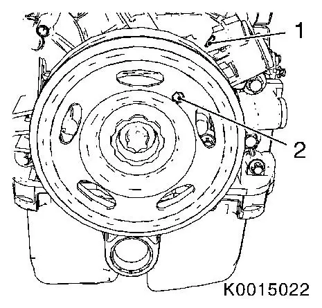
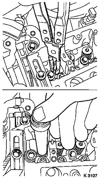
Adjust TDC of combustion stroke of cylinder 1
| • |
Marking on the ribbed V-belt pulley marker bore (2) must align
with the cast projection (1) on the timing case
|
|
|
|
| 11. |
Make alignment mark
| • |
On crankshaft belt pulley
Note: 180° offset
to marking TDC of combustion stroke cylinder 1.
|
|
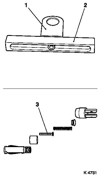
| 12. |
Prepare automatic valve spring lever MKM-6086
| • |
Adjust MKM-6086-6 supports (2)
| – |
Adjust support heads (1) so that they are centred in respect of
the support feet (2) and tighten
|
|
| • |
Complete lever arm MKM-6086-7
| – |
with joint MKM-6086-8 and dismantling
head MKM-6086-10
|
|
|
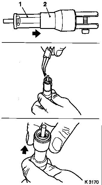
| 13. |
Complete assembly set MKM-6086-200
| • |
Insert thrust piece MKM-6086-200-11
(3)
Note: Follow
manufacturer's instructions
|
|
|
|
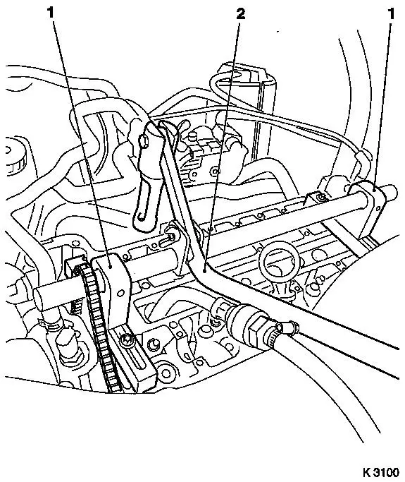
| 14. |
Attach automatic valve spring lever MKM-6086
| • |
Attach 2 supports MKM-6086-6 (1)
| – |
Push assembly shaft in the supports
Note: Align assembly
shaft centrally via spark plug bore.
|
|
| • |
Install lever arm MKM-6086-7 (2)
Note: Removal head must
point towards the intake side.
|
| • |
Secure installation shaft
|
|
|
|
| 15. |
Install compressed air adapter
| • |
Screw into spark plug thread of cylinder 1
|
| • |
Apply compressed air to cylinder 1
|
|
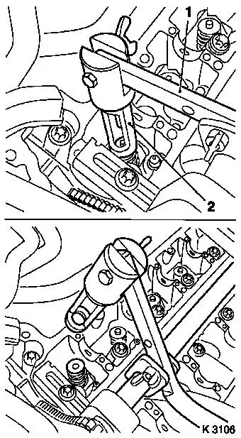
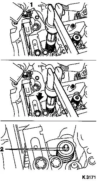
| 16. |
Remove 2 cylinder no.1 intake valve springs
| • |
Press valve spring carefully downwards with lever arm (1)
Note: Removal head (2)
must be positioned vertically over the valve stem.
|
Important: Note allocation.
|
| • |
Take out valve cotters, valve discs, valve springs
Note: Do not use any
magnetic tools.
|
|
|
|
| 17. |
Replace 2x valve stem seals
| • |
Place new valve stem seal on to valve stem
|
| • |
Drive in as far as the stop with KM-958
|
|
|
|
| 18. |
Install intake valve springs, cylinder 1
| • |
Insert valve springs and valve heads
|
| • |
Insert valve cotters into assembly head (1)
| – |
Slide plastic clamping sleeve (2) in direction of lever arm
mount
|
Important: Insert split cotters
with the narrow part facing the valve.
|
| – |
Insert valve cotters
|
| – |
Push plastic clamping sleeve in the direction of the valve
(arrow)
|
|
|
|
|
| 19. |
Install valve cotters
| • |
Attach assembly head (1) to lever arm
|
Important: Assembly head must
stand vertically above valve stem. Valve cotters (2) must engage
audibly.
Important: Do not
make a 2nd attempt without checking that both valve cotters are
seated in the assembly head. Check seat of valve cotters. Ensure
compressed air is being applied.
|
| • |
Press valve spring carefully downwards with lever arm
(arrow)
|
|
|
|
| 20. |
Transfer lever arm
| • |
Install lever arm
Note: Removal head must
point towards the exhaust side.
|
|
| 21. |
Remove 2 cylinder No.1 exhaust valve springs
| • |
Press valve spring carefully downwards with lever arm
Note: Removal head must
be vertical above the valve stem.
|
Important: Note allocation.
|
| • |
Take out valve cotters, valve discs, valve springs
Note: Do not use any
magnetic tools.
|
|
| 22. |
Replace 2x valve stem seals
| • |
Place new valve stem seal on to valve stem
|
| • |
Drive in as far as the stop with KM-958
|
|
| 23. |
Install 2 exhaust valve springs, cylinder 1
| • |
Insert valve springs and valve heads
|
| • |
Insert valve cotters into assembly head (1)
| – |
Slide plastic clamping sleeve (2) in direction of lever arm
mount
|
Important: Insert split cotters
with the narrow part facing the valve.
|
| – |
Insert valve cotters
|
| – |
Push plastic clamping sleeve in the direction of the valve
(arrow)
|
|
|
|
|
| 24. |
Install valve cotters
| • |
Attach assembly head to lever arm
|
Important: Assembly head must
stand vertically above valve stem. Valve cotters must engage
audibly.
Important: Do not
make a 2nd attempt without checking that both valve cotters are
seated in the assembly head. Check seat of valve cotters. Ensure
compressed air is being applied.
|
| • |
Press valve spring carefully downwards with lever arm
|
|
| 25. |
Transfer compressed air adapter
| • |
Interrupt compressed air feed
|
| • |
Unscrew from spark plug thread of cylinder 1
|
| • |
Screw into spark plug thread of cylinder 4
|
| • |
Apply compressed air to cylinder 4
|
|
| 27. |
Replace 4 valve stem seals, cylinder 4
|
| 28. |
Interrupt compressed air feed
|
| 29. |
Remove crankshaft lock KM-952
|
| 30. |
Adjust TDC of combustion stroke of cylinder 3
| • |
Pull timing chain upwards
|
| • |
Turn crankshaft evenly (180°)
Note: Marking made as
aid on crankshaft belt pulley must align with cast projection on
timing case.
|
|
| 31. |
Lock crankshaft with KM-952
|
| 32. |
Transfer compressed air adapter
| • |
Interrupt compressed air feed
|
| • |
Unscrew from spark plug thread of cylinder 4
|
| • |
Screw into spark plug thread of cylinder 2
|
| • |
Apply compressed air to cylinder 2
|
|
| 33. |
Replace 4 valve stem seals, cylinder 2
|
| 34. |
Transfer compressed air adapter
| • |
Interrupt compressed air feed
|
| • |
Unscrew from spark plug thread of cylinder 2
|
| • |
Screw into spark plug thread of cylinder 3
|
| • |
Apply compressed air to cylinder 3
|
|
| 35. |
Replace 4 valve stem seals, cylinder 3
|
| 36. |
Interrupt compressed air feed
|
| 37. |
Detach automatic valve spring lever
|
| 38. |
Remove compressed air adapter
|
| 39. |
Lock crankshaft
| • |
Pull timing chain upwards
|
| • |
Turn crankshaft evenly until KM-952
engages
|
|
 Install
| 40. |
Visually check components
| • |
Camshafts, camshaft bearing caps, cylinder head, roller cam
followers, hydraulic valve lifters
|
|
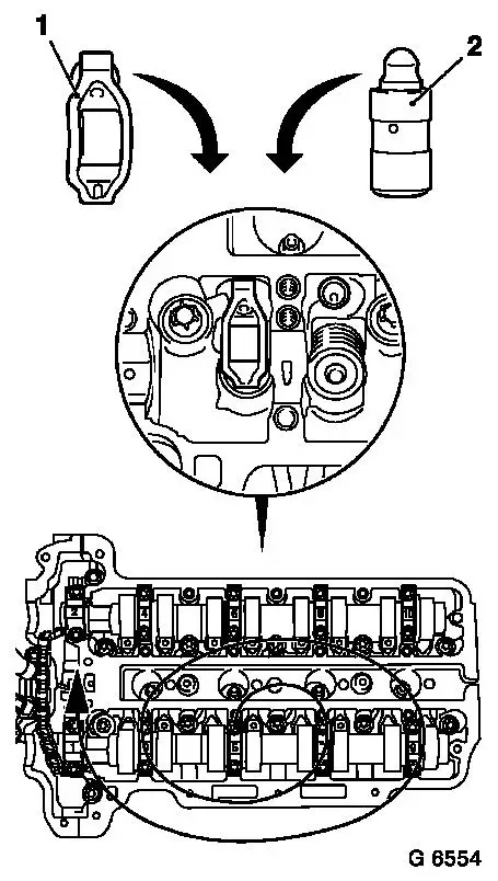
| 41. |
Check camshaft and camshaft bearing for wear
Note: If the camshaft
bearings are faulty, the cylinder head must be replaced. When
replacing the camshaft, the roller cam followers (1) and hydraulic
valve lifters (2) must be replaced.
|
|
|
| 42. |
Clean hydraulic valve lifters and coat with MoS2 sliding
paste
|
| 43. |
Insert hydraulic valve lifters in accordance with marked
allocation
|
| 44. |
Clean roller cam followers and coat with MoS2 sliding paste
|
| 45. |
Insert roller cam followers in accordance with marked
allocation
|
| 46. |
Install intake camshaft and exhaust camshaft
|
| 47. |
Clean phase sensor disk and camshaft sprocket
Note: The following
steps are to be performed to avoid rotating the phase sensor disc
when tightening the camshaft sprocket.
| • |
Clean the contact surface of the phase sensor disk to the
camshaft sprocket
|
| • |
Clean the contact surface of the camshaft sprocket to the phase
sensor disk
|
| • |
Lightly coat the bolt collar of the new bolt with engine
oil
|
|
| 48. |
Attach camshaft sprockets to camshafts
|
| 50. |
Attach sliding rail to cylinder head
|
| 51. |
Timing, Check
| • |
Turn crankshaft through 720°
| – |
Insert locking tool KM-952
|
|
| • |
Insert locking tool KM-953-A into
camshaft
|
| • |
Attach locating tool EN-49977-100 to
phase sensor discs
Note: If EN-49977-100 cannot be inserted, the operation
"timing, adjust" must be repeated
|
|
| 52. |
Detach locating tool EN-49977-100 and
locking tool KM-953-A
|
| 53. |
Remove locking tool KM-952
|
| 54. |
Tighten closure bolt crankshaft bearing bridge 50 Nm
|
| 55. |
Attach cylinder head cover
|
| 56. |
Install 4x spark plug
|
| 57. |
Install ignition module
|
| 58. |
Install air cleaner housing
|
|
