|
Replace shift or selector position sensor (M20
MTA)
 Remove Remove
Important: Follow Easytronic
safety notes .
Before working on the M20-MTA high pressure system, it is essential
to reduce the MTA system pressure (approx. 40 - 60 bar).
|
| 1. |
Reduce MTA system pressure
|
| 3. |
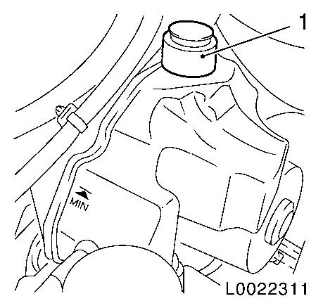
Drain CS Speed oil reservoir
| • |
Unscrew closure cap (1)
|
| • |
Extract CS-Speed oil with suitable tool
|
|
|
|
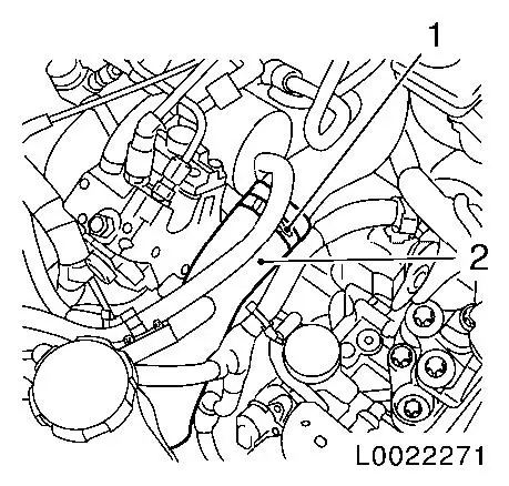
| 4. |
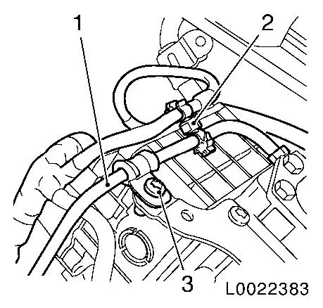
Pull off top charge air hose (2)
|
|
|
| 5. |
Detach holder for high pressure line MTA system (1)
|
|
|
| 6. |
Place collecting basin underneath.
|
| 7. |
Separate high pressure line on clutch module
|
|
|
Important: The electronic control
unit may only be removed and reinstalled once. If the electronic
control unit is removed again, it must be replaced.
|
| 8. |
Remove electronic control unit 
|
| 9. |
Detach high pressure line clip on shift module bracket
|
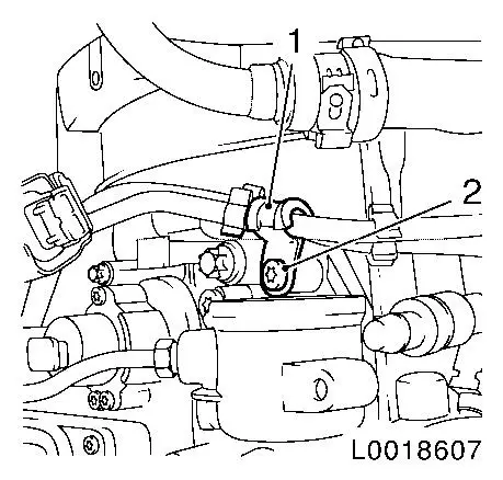
| 10. |
Unclip wiring harness (2) from high pressure line (1)
|
|
|
| 11. |
Detach high pressure line (1) from the shift module
|
|

|
| 12. |
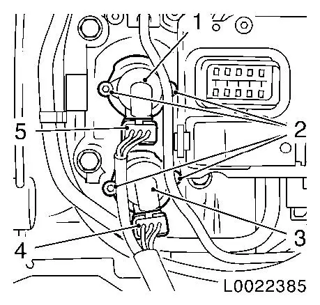
Remove sensor for shift (3) or selection position (1)
Note: Note installation
position
| • |
Release wiring harness plug (4) or (5) and separate.
|
|
|
|
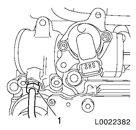
| 13. |
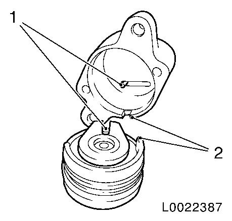
Pull out drive (1) for shift or selection position sensor from
shift module
|
|

|
 Install
| 14. |
Fit drive for shift or selection position sensor
| • |
Lightly grease actuator lever on drive
|
| • |
Bring drive into correct installation position (1)
|
| • |
Insert drive into shift module and press in up to stop
Note: Marking on shift
module and drive must match (2).
After pressing the drive into the shift module, by twisting the
drive ensure that this is correctly seated.
Do not allow drive pin for sensor to twist.
|
|
|
|
| 15. |
Attach sensor for shift or selection position
| • |
Place sensor on drive and pretension spring in sensor by
twisting clockwise (arrow).
|
| • |
Tighten 2x bolts 3.6 Nm
|
|
|

|
| 16. |
Attach sensor for shift (3) or selection position (1)
replaced
| • |
Tighten 2 bolts (2) 3.6 Nm
|
| • |
Connect and latch wiring harness plug (4) or (5)
|
|
|
|
| 17. |
Detach high pressure line (1) on shift module
| • |
Tighten union nut (2) 14 Nm
|
|
|
|
| 18. |
Attach high pressure line clip to shift module bracket
|
| 19. |
Clip in wiring harness (2) on high pressure line (1)
|
|
|
| 20. |
Install remove electronic control unit
|
| 21. |
Connect high pressure line to clutch module
| • |
Tighten union nut (1) 14 Nm
|
|
|
|
| 22. |
Attach holder for high pressure line MTA system (1)
|
|
|
| 23. |
Push on top charge air hose (2)
|
|
|
| 25. |
Install battery tray and battery
|
| 26. |
Necessary commissioning routines for Easytronic
|
| 27. |
Program volatile memories
|
|
