|
Engine, Remove and Install
The operation "Engine, Remove and Install" is described for an X
25 DT engine with manual transmission and LHD. Proceed analogously
for other engine and equipment versions.
Cable ties which are released or detached for removal of the
engine must be re-installed in the same position during
installation.
 Remove Remove
In vehicles with AC: Drain AC – see operation "AC, Drain"
in group "D".
|
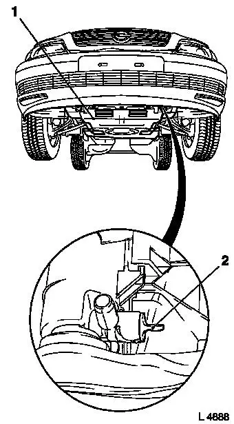
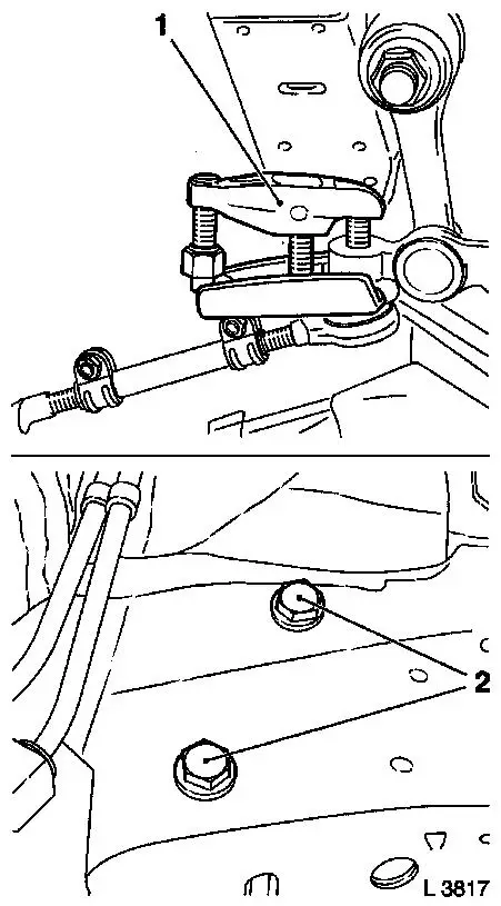
Detach lower engine compartment cover (1).
Open coolant drain bolt (2) on radiator – collect escaping
coolant.
|
|
|
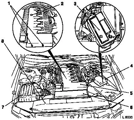
If present: Remove radiator damper (3 parts) (8).
Unclip fuse carrier (4) from relay frame and lay aside.
Disconnect battery (3) and remove.
Remove air cleaner housing (7) – see operation "Air
Cleaner Housing, Remove and Install (25 DT)" or "Air Cleaner
Housing, Remove and Install (X 25 DT)".
Open quick fitting bolts (1), remove fastening nut (2) and
remove upper engine compartment cover.
Remove charge air pipe (6) – see operation "Charge Air
Pipe, Remove and Install".
|
|
Remove visco-fan – see operation "Visco-fan, Remove and
Install".
|
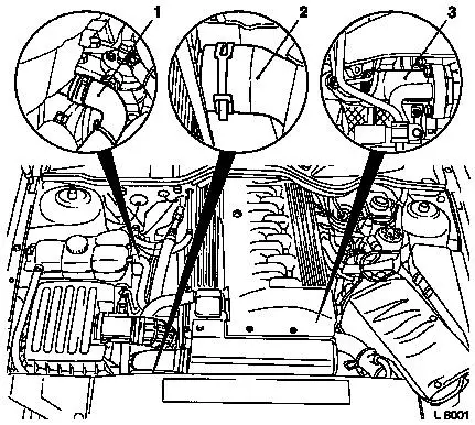
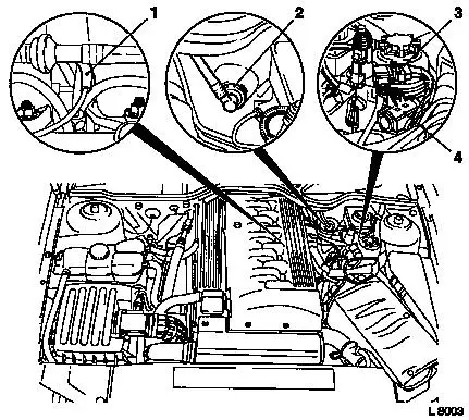
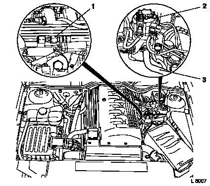
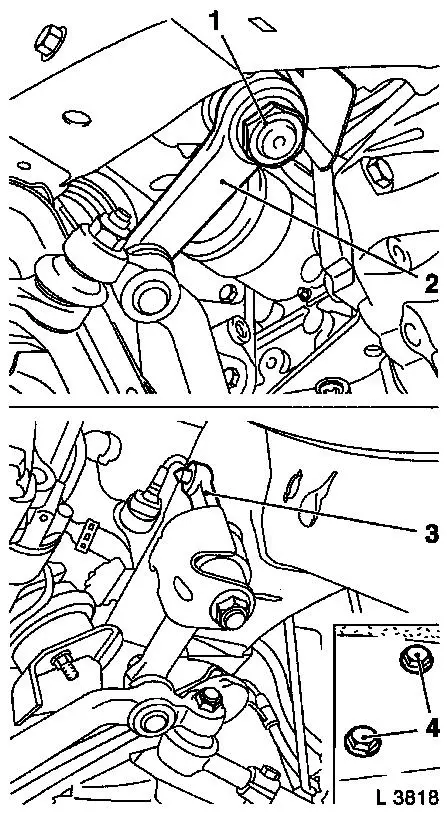
Detach coolant hose (3) from cylinder head.
Detach coolant hose (2) from radiator.
Detach coolant hose (1) from coolant compensation tank.
|
|
|
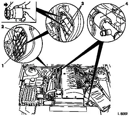
Remove fastening bolt (2) and remove service flap (1).
Release coolant hoses (3) in direction of arrow and detach from
heater core.
Disconnect refrigerant lines at the separation points (4) with
KM-917.
|
|
|
Detach brake servo vacuum line (2) from brake servo.
Remove vacuum line (1) from T-piece and expose.
Mark vacuum line and detach from electro-pneumatic pressure
transducer (4).
Detach vacuum line from charge pressure sensor (3).
|
|
|
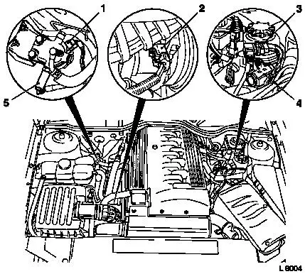
Disconnect wiring harness plug (5) from temperature switch.
Detach wiring harness plug (1) from filter heating.
Detach wiring harness plug from electro-pneumatic pressure
transducer (4).
Detach wiring harness plug (3) from charge pressure sensor.
Remove wiring harness plug (2) from compressor.
|
|
|
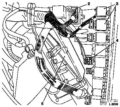
Detach multiplug (1) (turn lock).
Detach fastening bolts (2) from positive terminal.
Remove fastening bolt (3) from ground terminal.
Remove relay frame cover (4)
|
|
|
Detach wiring harness plugs (2) and (4).
Remove relay (3) with socket out of relay frame.
Remove engine control unit (5) out of relay frame.
Remove compete wiring harness (1) out of relay frame and lay
engine control unit on engine.
|
|
|
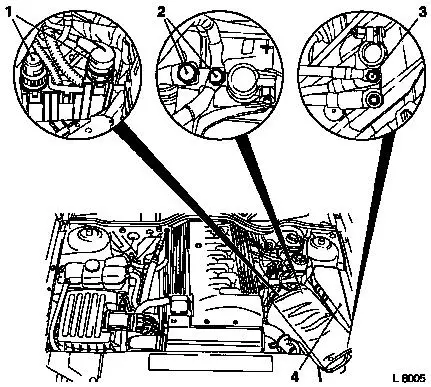
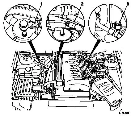
Siphon off hydraulic fluid from power steering fluid reservoir
(2) with siphon bottle.
Detach hydraulic hose (3) from power steering fluid reservoir
– collect escaping hydraulic fluid.
Disconnect power steering hydraulic line (1) – collect
escaping hydraulic fluid.
|
|
Caution
Fuel escapes. Observe safety regulations and national
legislation.
|
Remove
Detach fuel feed line (1) from fuel filter – collect
escaping fuel.
Detach fuel return line (2) from fuel return pipe –
collect escaping fuel.
Top up brake fluid reservoir completely and close off with dummy
plug.
Open retaining strap (3) for connecting piece on bulkhead.
|
|
Detach retaining clip and disconnect clutch actuation pressure
line – collect escaping brake fluid – re-use retaining
clip.
|
Remove fastening bolt (1) and disconnect engine oil lines
– collect escaping engine oil.
Detach charge air hose (3) from intercooler.
Detach front exhaust pipe (2).
Front Wheels, Remove.
|
|
|
Detach fastening nuts from tie rods and release left and right
tie rods with KM-507-C (1) – do not remove yet.
Release idler bracket fastening bolts (2) – do not remove
yet.
|
|
|
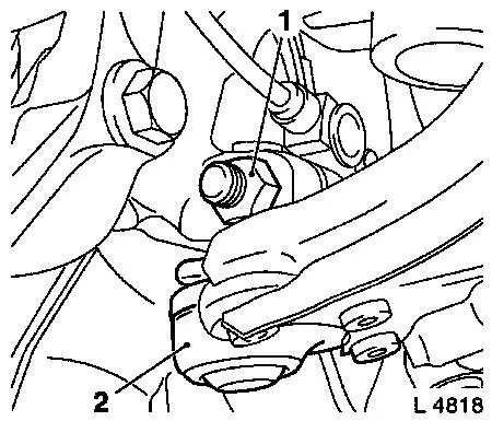
Detach cover cap from steering arm fastening nut (1).
Detach steering arm fastening bolt.
Mark installation position of steering arm.
Press out steering arm (2) with KM-146-01.
Remove fastening nuts (4) from idler bracket (3) and remove
entire steering linkage.
|
|
|
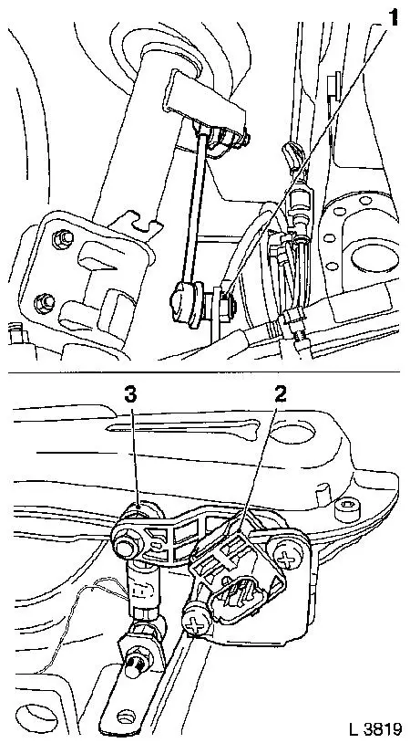
Detach fastening nuts for link rod (1) on both sides from
stabiliser – counterhold with open-ended spanner at the
flattened surfaces.
For vehicles with xenon headlamp:
Disconnect vehicle level control sensor wiring harness (2).
Remove ball head (3) from vehicle level control sensor.
|
|
|
Detach fastening nuts (1) and remove fastening bolts.
Pull guide joint (2) downwards out of steering knuckle.
Detach propshaft from transmission flange and push to the
rear.
|
|
|
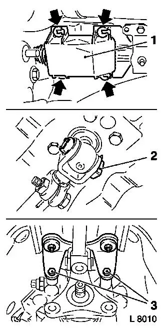
Remove 4 clips (arrows) from cover (1) on shift outrigger.
Push cover forwards.
Slide retainer (2) from pin.
Pull pin out from shift rod and fork.
Detach fastening bolts (3) from shift outrigger.
|
|
|
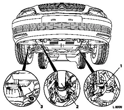
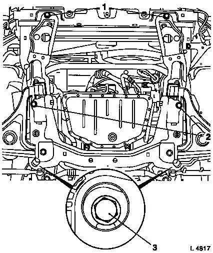
Note: Before
positioning the Centring Mount KM-6190, the split pins of the
centring pins (1) and (3) must be pulled out so that the centring
pins cannot engage in the corresponding mounts.
Install Base Frame KM-904-B with Centring Mount KM-6190 on
hydraulic jack and position without play under front axle body
– ensure that the centring pins (2) and (4) sit in the
corresponding mounts (use hydraulic jack which can be lowered to at
least 100 cm).
Important: Removal
of the front axle body with an impulse or impact screwdriver is not
permissible. Note various lengths of bolts.
|
|
|
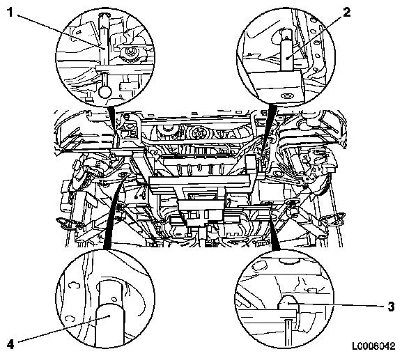
Unscrew transmission holder from underbody.
Remove front fastening bolts (1), centre fastening bolts (2) and
rear fastening bolts (3).
Carefully lower front axle body with engine and
transmission.
|
|
|
Important: Ensure
the threads of the captive nuts move freely before installing front
axle body with engine and transmission, replace captive nuts if
necessary.
Note: Before
installing the engine, the centring pins (1) and (3) must be pushed
up and secured with the corresponding split pins.
 Install
Carefully move drive unit into engine compartment until centring
pins (1) and (3) engage in the corresponding mounts of the
underbody – ensure that no attaching parts are damaged.
|
|
|
Install
Insert new fastening bolts for front axle body to front member
and side member.
Tighten fastening bolts (1) for front of front axle body to
front member – tightening torque 65 Nm / 48 lbf. ft. +
30° + 15°.
Tighten fastening bolts (2) for centre of front axle body to
side member – tightening torque 150 Nm / 111 lbf. ft. +
30° + 15°.
Tighten fastening bolts (3) for rear of front axle body to side
member – tightening torque 130 Nm / 96 lbf. ft. + 30° +
15°.
|
|
Attach transmission holder to underbody – tightening
torque 45 Nm / 33 lbf. ft. 1)
.
Remove
Lower hydraulic jack and detach Base Frame KM-904-B and Centring
Mount KM-6190 from hydraulic jack.
Install
Attach shift outrigger to transmission – tightening torque
20 Nm / 15 lbf. ft.
Attach shift outrigger to shift lever and attach cover.
Attach propshaft to transmission flange – tightening
torque 95 Nm / 70 lbf. ft.
Connect guide joints to steering knuckle – tightening
torque 100 Nm / 74 lbf. ft.
For vehicles with xenon dipped beam: Attach ball head and wiring
harness plug to vehicle level control sensor.
Attach link rods to stabiliser – tightening torque 65 Nm /
48 lbf. ft.
Attach idler bracket to body – tightening torque 55 Nm /
41 lbf. ft. + 75° + 15° 2) .
Attach steering arm to steering shaft with new fastening nut
– note mark – tightening torque 160 Nm / 118 lbf.
ft.
Attach cover cap to steering arm fastening nut.
Connect left and right tie rods to steering knuckle with new
fastening nuts – tightening torque 60 Nm / 44 lbf. ft.
Attach front wheels – tightening torque 110 Nm / 81 lbf.
ft.
Install front exhaust pipe with new seal ring and new fastening
nuts.
Attach charge air hose to intercooler – tightening torque
– 3.5 Nm / 2.6 lbf. ft.
Connect engine oil lines with new gaskets.
Connect clutch actuation pressure line and fasten retaining
band.
Attach fuel return line to fuel return pipe.
Attach fuel feed lines with new gaskets to fuel filter –
tightening torque 15 Nm / 11 lbf. ft.
Connect power steering hydraulic line.
Attach hydraulic line to power steering fluid reservoir.
Insert wiring harness into relay frame.
Install engine control unit in relay frame.
Install relay with socket in relay frame – x3.
Connect wiring harness plug in relay frame – x2.
Install relay frame cover.
Attach all cable connections to ground cable and positive
terminal – ensure correct routing of cables.
Connect multiplug (twist lock) – x2.
Attach wiring harness plug to compressor.
Attach wiring harness plug to charge pressure sensor.
Attach wiring harness plug to electro-pneumatic pressure
transducer.
Attach wiring harness plug to filter heating.
Connect wiring harness plug to temperature switch.
Attach vacuum line to charge pressure sensor.
Attach vacuum line to electro-pneumatic pressure transducer
– note marks.
Route heater vacuum line and attach to T-piece.
Attach brake servo vacuum line to brake servo.
Connect refrigerant lines with new gaskets – 2 separation
points.
Attach coolant hoses to heater core – x2.
Install service flap.
Connect coolant hose to coolant compensation tank.
Attach coolant hose to radiator.
Attach coolant hose to cylinder head.
Install visco-fan – see operation "Visco-fan, Remove and
Install".
Install charge air pipe – see operation "Charge Air Pipe,
Remove and Install".
Install upper engine cover.
Install air cleaner housing – see operation "Air Cleaner
Housing, Remove and Install (25 DT)" and "Air Cleaner Housing,
Remove and Install (X 25 DT)".
Install battery on battery support.
Attach battery terminals to battery.
Clip fuse carrier to relay frame.
If present: install radiator damper (3 parts).
Clip coolant hose into fan housing.
Close coolant drain bolt.
Bleed hydraulic clutch actuation – see operation
"Hydraulic Clutch Actuation, Bleed " in group "K".
Top up power steering fluid reservoir – see operation
"Hydraulic System, Charge" in group "M".
Vehicles with air conditioning: Charge air conditioning –
see operation "Air Conditioning, Evacuate and Charge" in group
"D".
 Inspect
Top up cooling system – see operations "Cooling System,
Top Up and Bleed" and "Cooling System, Check for Leaks".
Install
Install lower engine compartment cover - tightening torque 5 Nm
/ 3.7 lbf. ft.
1 ) Clean thread and insert with bolt locking
compound (red).
2 ) Use new bolts.
|
