|
Removing and installing assemblies
Illustrations
|
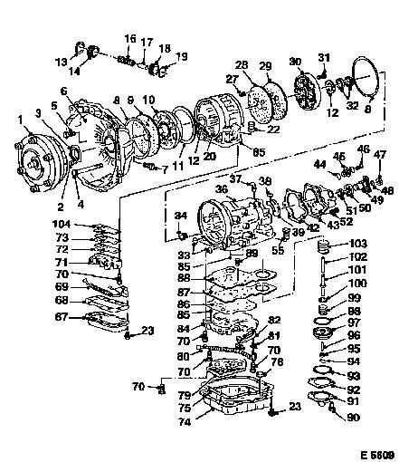
Survey of Assemblies, AR 25/35
Illustration shows torque converter
for 4- and 6-cylinder petrol engines.
|
1
|
Torque converter with converter clutch
|
|
2
|
Fastening bolt, seal ring/converter housing
|
|
3
|
Seal ring, converter housing
|
|
4
|
Fastening bolt, converter housing/transmission casing
|
|
5
|
Fastening bolt, converter housing/fluid pump (x 5)
|
|
6
|
Converter housing
|
|
7
|
Closure screw, fluid pressure checking bore hole
|
|
8
|
O-ring
|
|
9
|
Support plate, fluid pump
|
|
10
|
Fluid pump
|
|
11
|
Gasket
|
|
12
|
Thrust washer (selectable)
|
|
13
|
Retaining ring
|
|
14
|
Closure cap, 3/4 accumulator
|
|
|
|
Survey of Assemblies, AR 25/35
(Continued)
|
16
|
Spring for piston, 3/4 accumulator
|
|
18
|
Piston, 3/4 accumulator
|
|
19
|
Seal ring for piston, accumulator
|
|
20
|
Intermediate housing
|
|
22
|
Connector, intermediate housing
|
|
23
|
Fastening bolt
|
|
27
|
Throttle
|
|
28
|
Gasket, support plate
|
|
29
|
Support plate, centre support
|
|
30
|
Centre support
|
|
31
|
Fastening bolt
|
|
32
|
Seal ring, centre support
|
|
33
|
O-ring, transmission housing
|
|
|
|
Survey of Assemblies, AR 25/35
(Continued)
|
34
|
Connection, fluid cooler line (transmission outlet)
|
|
36
|
Transmission housing
|
|
37
|
Vent
|
|
38
|
Seal ring, fluid reservoir
|
|
39
|
Fluid reservoir
|
|
42
|
Gasket, nose piece
|
|
43
|
Nose piece
|
|
44
|
O-ring, sensor
|
|
45
|
Transmission output speed sensor
|
|
46
|
Fastening bolt
|
|
47
|
Fastening nut, output flange
|
|
48
|
O-ring, output flange
|
|
49
|
Output flange
|
|
50
|
Seal ring, nose piece
|
|
51
|
Radial needle roller bearing
|
|
|
|
Survey of Assemblies, AR 25/35
(Continued)
|
52
|
Fastening bolt, extension (x 7)
|
|
55
|
Connector, transmission housing
|
|
67
|
Transmission fluid pan, intermediate housing
|
|
68
|
Gasket, intermediate housing
|
|
69
|
Wiring harness, intermediate housing
|
|
70
|
Fastening bolt, valve body assembly (x 19)
|
|
71
|
Valve body assembly, intermediate housing
|
|
72
|
Gasket
|
|
73
|
Support plate
|
|
74
|
Transmission fluid pan, transmission housing
|
|
75
|
Gasket, transmission housing
|
|
78
|
Fixing magnet
|
|
|
|
Survey of Assemblies, AR 25/35
(Continued)
|
79
|
Fluid strainer
|
|
80
|
Wiring harness, transmission housing
|
|
81
|
Bracket
|
|
82
|
Detent spring
|
|
84
|
Valve body assembly
|
|
85
|
Valve balls (2 balls on underside of transmission housings, 1
ball in transmission housing valve body, 1 ball on underside of
intermediate housings)
|
|
|
|
Survey of Assemblies, AR 25/35
(Continued)
|
86
|
Gasket
|
|
87
|
Support plate
|
|
88
|
Gasket
|
|
89
|
Fastening bolt, support plate (x 2)
|
|
90
|
Fastening bolt, brake band servo cover (x 4)
|
|
91
|
Brake band servo cover
|
|
92
|
Gasket
|
|
93
|
Retaining ring
|
|
94
|
Retaining clamp
|
|
95
|
Lock nut
|
|
96
|
Adjustment bolt
|
|
|
|
Survey of Assemblies, AR 25/35
(Continued)
|
97
|
Brake band servo piston
|
|
98
|
Piston ring
|
|
99
|
Cushion spring
|
|
100
|
Seat, damping spring
|
|
101
|
Sleeve
|
|
102
|
Cam follower
|
|
103
|
Relief spring, servo piston
|
|
104
|
Gasket, support plate/intermediate housing
|
|
|
Illustration
|
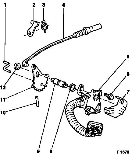
Automatic transmission AR 25/35,
parking lock and selector lever position switch
|
1
|
Control lever
|
|
2
|
Pawl
|
|
3
|
Retaining spring
|
|
4
|
Actuation rod, parking lock
|
|
5
|
Selector lever position switch
|
|
6
|
Fastening bolt (x 2)
|
|
7
|
Cover plate
|
|
8
|
Seal ring
|
|
9
|
Transmission selector lever shaft
|
|
10
|
Roll pin
|
|
11
|
Shift segment
|
|
12
|
Fastening nut
|
|
|
 Remove Remove
Remove transmission – see operation "Automatic
Transmission, Remove and Install (Vehicles with 4-Cylinder Petrol
Engine)", "Automatic Transmission, Remove and Install (Vehicles
with V6 Engine)", "Automatic Transmission, Remove and Install
(Vehicles with Diesel Engine)".
Note: During all
operations on automatic transmission ensure utmost cleanliness of
the components and tools. Malfunctioning of the transmission is
often caused by dirt and foreign objects.
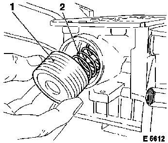
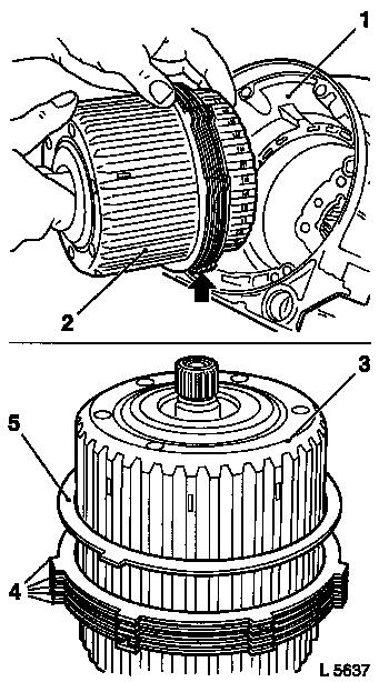
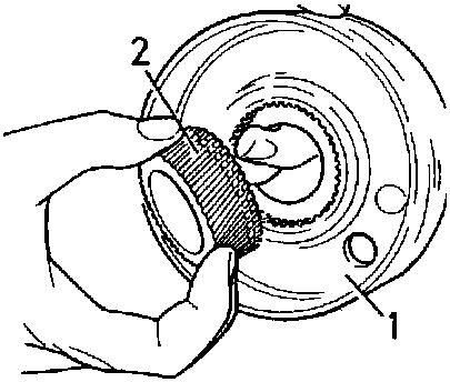
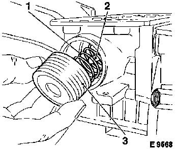
Caution
|
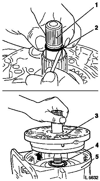
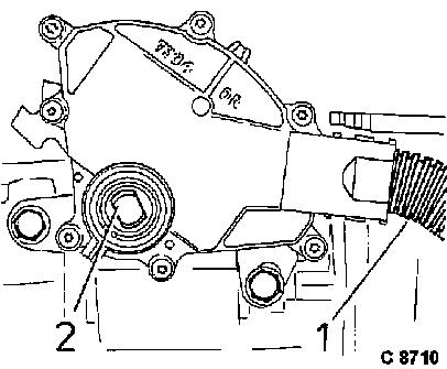
Converter contains a large amount of transmission fluid.
Transmission fluid escapes. Place collecting basin
underneath.
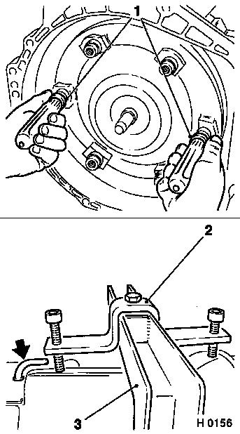
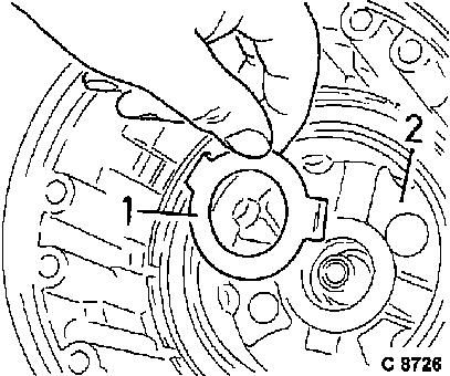
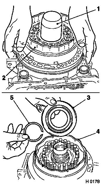
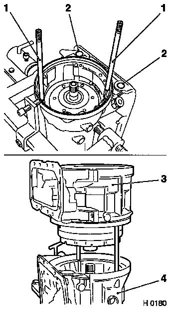
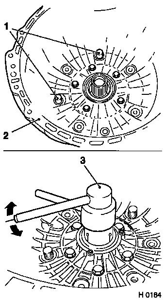
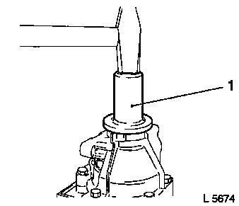
Remove
Remove converter with KM-574 (1) or KM-899 (vehicles with diesel
engine) from converter housing.
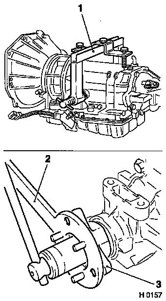
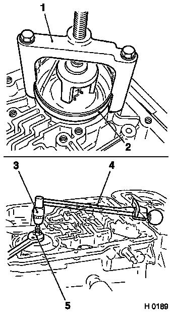
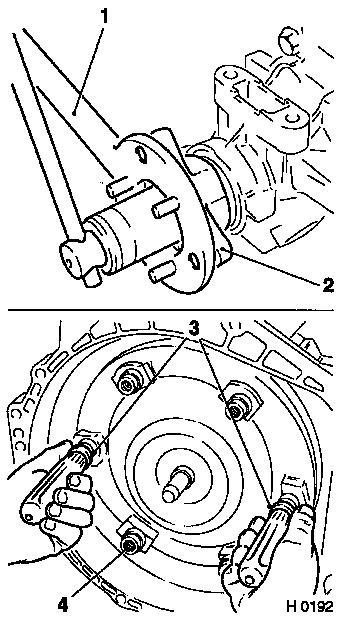
 Install
Attach KM-113-A (3) in conjunction with KM-113-5 (2) to
transmission.
Attach assemblies to KM-113-2.
Install short arm of KM-113-5 towards output side, so that vent
line (arrow) remains free.
|
|
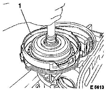
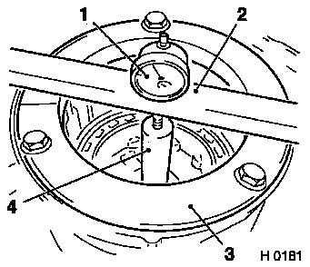
Caution
|
Do not press too heavily on transmission holder (1), since
otherwise the assemblies cannot be removed – the transmission
housing would be deformed.
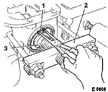
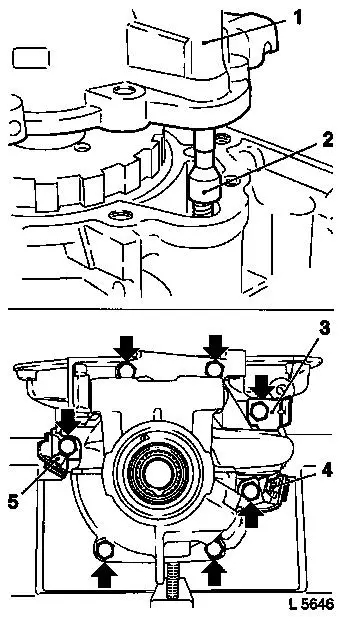
Remove
Remove fastening nut for output flange (socket A/F 30, extra
long), counterhold with KM-623 (2).
Detach output flange (3) from the output shaft. If stiff, detach
with KM-628-A.
 Inspect
Check O-ring of output flange for wear and damage, replace if
necessary.
|
|
Caution
|
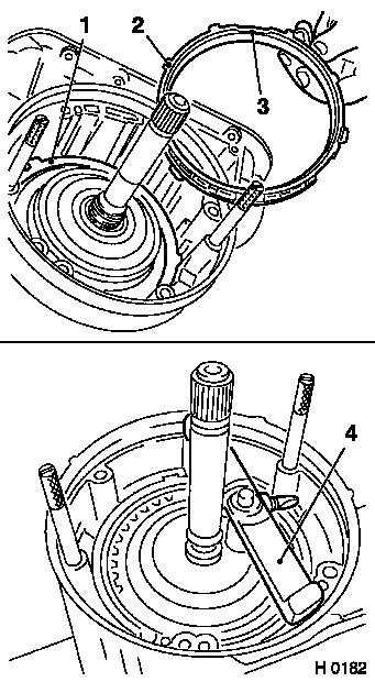
Turn transmission carefully with KM-113-A (4), so that any dirt
present (shavings) cannot fall into the valve body.
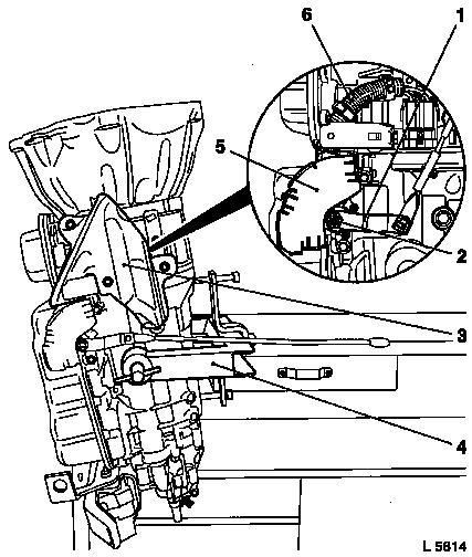
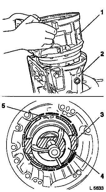
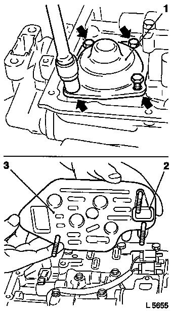
Remove
Converter housing points upwards.
Drain remaining transmission fluid through extension
(arrow).
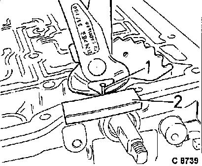
Remove heat shield (3) for selector lever position switch (3
fastening bolts).
Remove selector intermediate lever (1) from the transmission
selector lever shaft (2) (1 fastening nut).
Detach selector lever position switch with shield (5) and wiring
harness (6) from the transmission selector lever shaft (2 fastening
bolts).
|
|
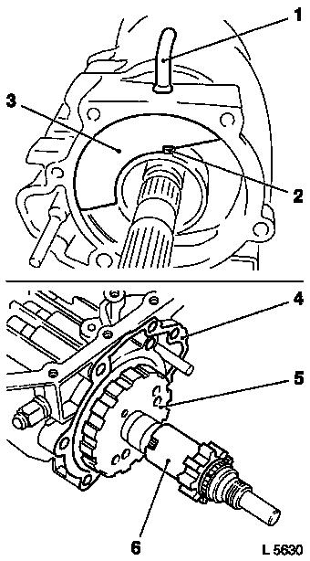
|
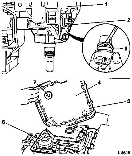
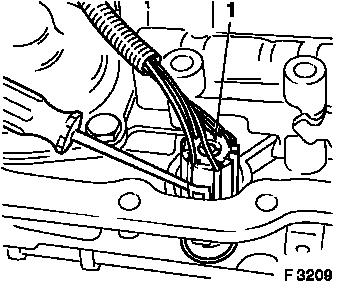
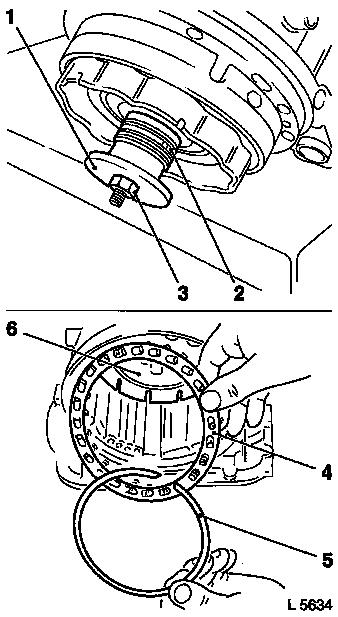
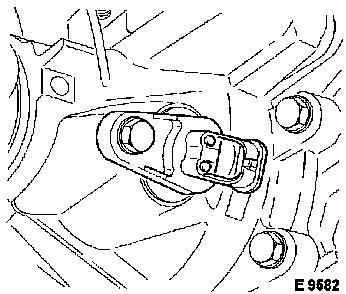
Detach transmission output speed sensor (2) from transmission
extension (1) (1 fastening bolt).
Inspect
Replace O-ring (3) in transmission output speed sensor.
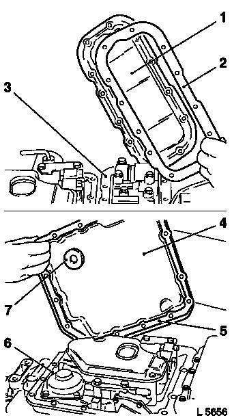
Remove
Turn transmission – transmission fluid pans point upwards.
Detach transmission fluid pan (4) and gasket (5) from transmission
main casing (6) (16 fastening bolts).
 Clean Clean
Remove fixing magnet (7) from the transmission fluid pan. Clean
inside of transmission fluid pan, transmission fluid pan sealing
surfaces and fixing magnet.
|
|
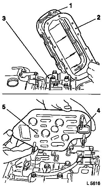
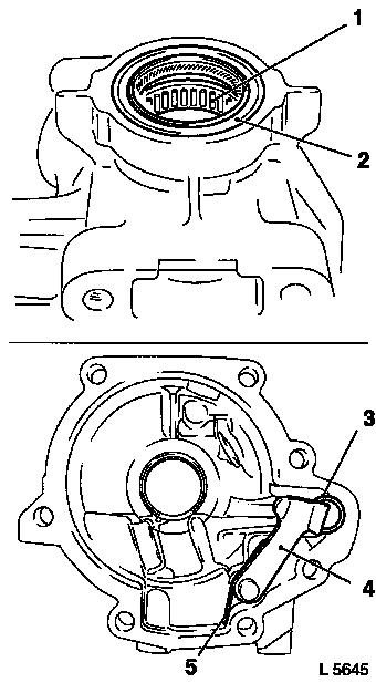
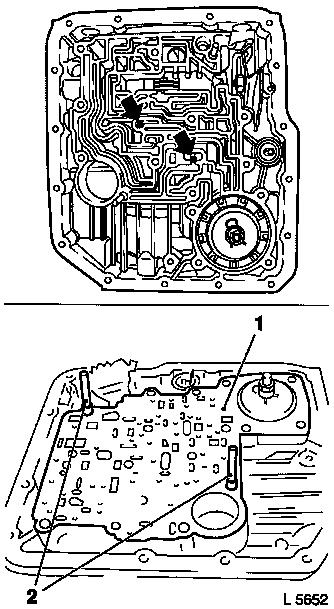
Remove
|
Detach transmission fluid pan (1) and gasket (2) from
transmission intermediate casing (3) (12 fastening bolts).
Clean
Clean transmission fluid pan sealing surface and inside of
transmission fluid pan.
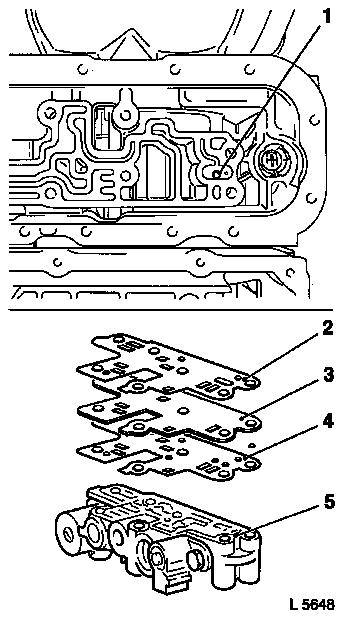
Remove
Detach fluid screen (5) with stuck-on gasket (4) (3 fastening
bolts).
|
|
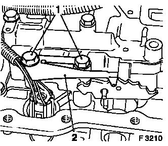
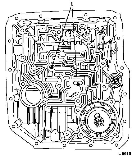
|
Remove fastening bolts (1) and remove detent spring (2).
|
|
|
Caution
Do not pull on wiring harness.
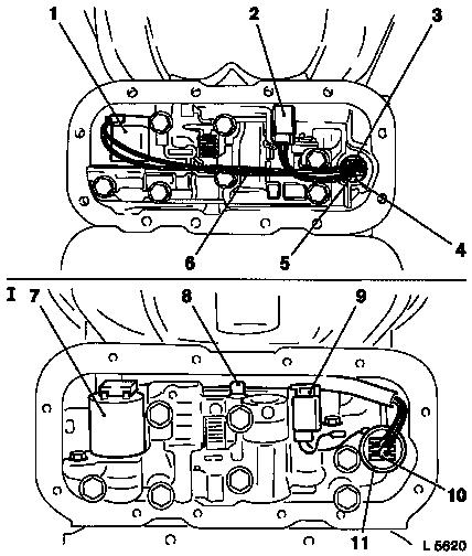
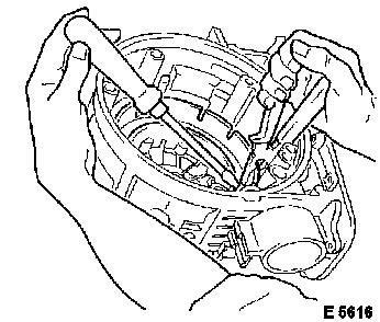
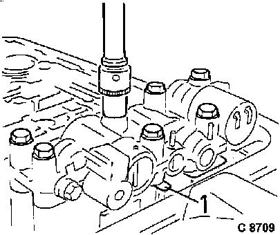
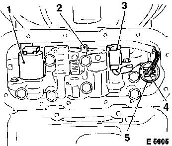
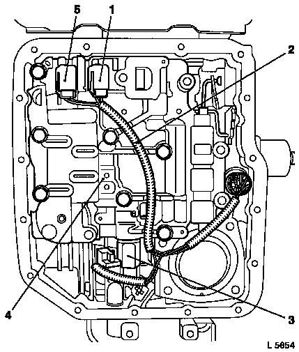
Remove
Carefully release 7-pin wiring harness plug (1) for solenoid
valves from transmission housing connection plug with small
screwdriver and disconnect.
|
|
Caution
|
Do not pull on the cables of the wiring harness.
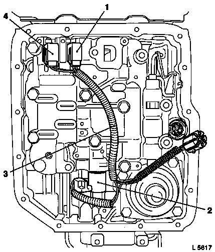
Remove
Detach plug connection at solenoid valve (2) for brake band
servo.
Detach plug connection at solenoid valve (4) for 1/2 shifting
and 3/4 shifting.
Detach plug connection at solenoid valve (1) for 2/3
shifting.
Remove wiring harness (3) for main casing valve body.
|
|
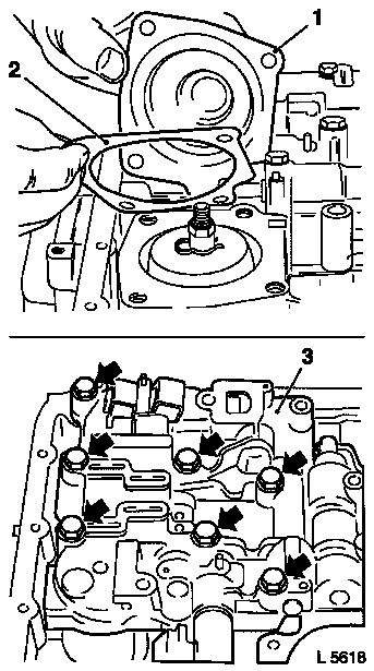
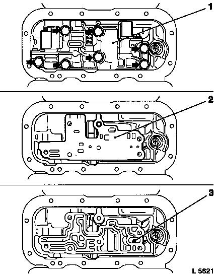
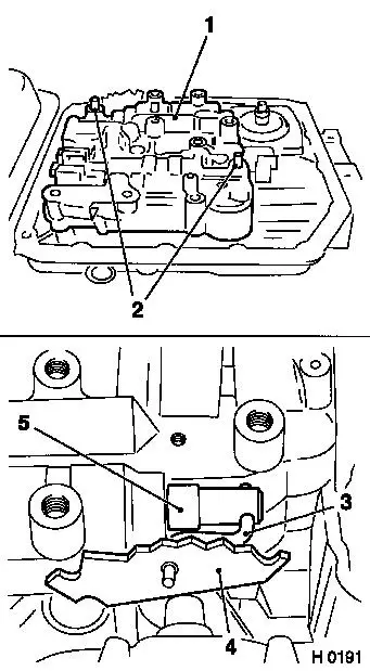
|
Detach brake band servo cover (1) and gasket (2) (4 fastening
bolts).
Detach fastening bolts (arrows) for valve body assembly (3).
|
|
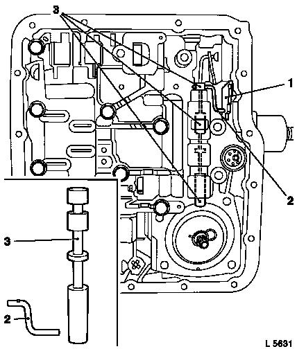
|
Lift valve body assembly and detach control lever (2) for shift
valve (3) on shift segment (1).
Remove valve body assembly with intermediate plate and gasket.
Do not reuse gasket.
Remove shift valve (2) with control lever (1) from valve body
assembly.
Note position of control lever (1). Long end points towards
selector valve (2).
|
|
Caution
|
Do not lose valve balls.
To remove, do not use any magnets because the valve balls will
become magnetic and will attract any resulting shavings, which may
lead to leaks in the fluid circuit in question or to
malfunctions.
Remove
Remove valve balls (1) from the fluid ducts of the transmission
main casing.
|
|
Caution
|
Do not pull on the cables of the wiring harness.
Remove
Detach plug connection at solenoid valve for pressure regulator
(1).
Detach plug connection at solenoid valve for converter clutch
(2).
Detach wiring harness plug (5) from connection plug (4) on
intermediate casing.
Remove wiring harness for intermediate casing valve body
(6).
If present (L 5620 I), pull out sheathed part of wiring harness
until wiring harness plug for pressure regulator solenoid valve (7)
can be removed past the retaining lug (8).
|
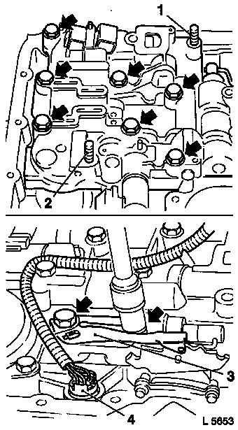
|
|
Detach fastening bolts (arrows) for valve body assembly (1) from
intermediate casing.
Detach valve body assembly with support plate (2) and both
gaskets beneath.
Caution
Do not lose valve ball.
To remove, do not use any magnets because the valve ball will
become magnetic and will attract any resulting shavings, which may
lead to leaks in the fluid circuit in question or to
malfunctions.
Remove
Remove valve body (3) from the fluid duct of the transmission
intermediate casing.
|
|
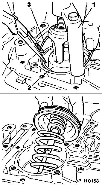
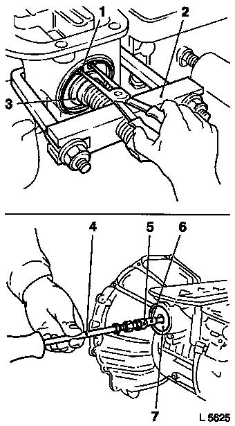
|
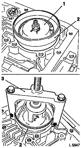
Remove servo piston assembly (2).
Attach KM-J-23075-A (1) to transmission casing. KM-J-23075-A has
a symmetrical design, attach in the position shown.
Compress relief spring for brake band servo piston with spring
compressor. Slowly relieve tension on KM-J-23075-A (high spring
tension) and remove.
Remove retaining ring (3) and remove servo piston assembly.
Inspect
Check servo piston assembly for wear and damage, replace with
new parts, if necessary.
|
|
Remove
|
Detach fastening bolts (arrows) and wiring harness bracket (1, 2
and 3) if fitted.
Detach transmission extension (4) with gasket below from
transmission casing.
Remove pawl (6) for parking lock with retaining spring (7) from
transmission extension.
Inspect
Check liner (5), pawl and retaining spring for wear and damage,
replace if necessary.
|
|
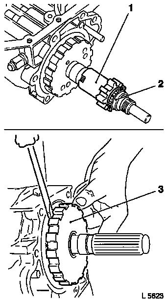
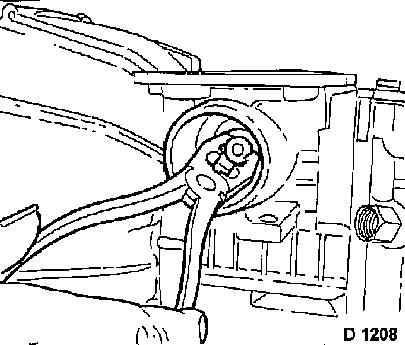
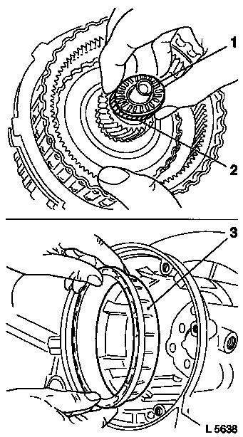
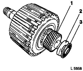
Remove
|
Detach pulse pickup (1) for output speed sensor from the output
shaft (2).
Detach parking lock gear (3) from output shaft using
screwdriver.
|
|
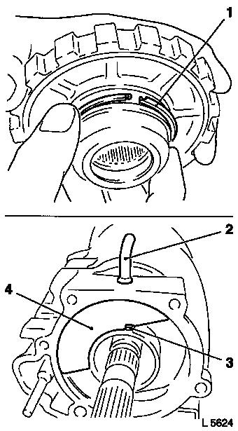
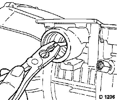
Inspect
|
Check parking lock gear for wear and damage.
Check hook seal ring (1) on hub of parking lock gear for
breakage and wear, replace if necessary.
Remove
Clamp vent pipe (2) with pliers and remove from transmission
casing. Avoid damage.
Remove fluid reservoir (4). Installation position is determined
by the guide (3).
|
|
|
Attach KM-686-1 (2) and KM-469-14 (3) to the intermediate casing
to remove the 3/4 accumulator piston. The short side of remover
bridge points to the converter housing.
Compress accumulator spring with KM-469-14 (3) until the
retaining ring is free. Remove retaining ring (1) – do not
damage ring groove in the process.
Relieve tension on KM-686-1 and detach.
Remove closure cap (7) for the accumulator piston with KM-686-2
(5) in conjunction with KM-838 (6) and KM-J-7004 (4).
Prevent tilting of the closure cap by aligning the tools at an
angle.
Release closure cap with light taps of a soft metal drift and
plastic hammer.
|
|
|
Remove closure cap (1) and spring (2) for accumulator
piston.
|
|
|
Remove pin using suitable pliers.
|
|
Remove
|
Remove piston for 3/4 accumulator using pliers.
Doing this, do not tilt piston.
|
|
|
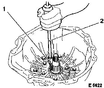
For further disassembly, turn transmission in adapter by 90°
(converter housing upwards).
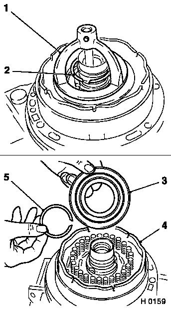
Release cover of seal ring for fluid pump (3 fastening
bolts).
|
|
Remove
|
Drive seal ring out of converter housing with KM-J-23129 or
KM-586 (1) in conjunction with KM-J-7004 (2).
If seal ring is difficult to remove, remove after removal of
converter housing.
|
|
|
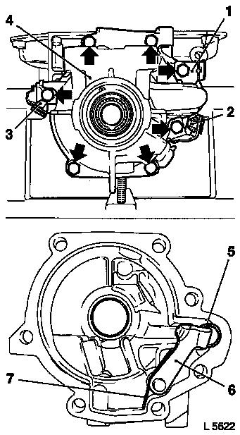
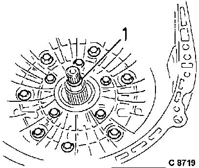
Detach fastening bolts for converter housing (outer screw circle
– 7 fastening bolts).
Detach fastening bolts for fluid pump (inner screw circle
– 5 fastening bolts).
Detach converter housing from intermediate casing by gently
turning back and forth, as well as from drive shaft and fluid pump
shaft (1).
|
|
|
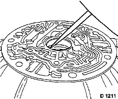
Note: Operation is
only necessary if seal ring in converter housing could not be
removed using KM-J-23129 or KM-586.
Remove
Drive out seal ring from converter housing using suitable
screwdriver.
|
|
|
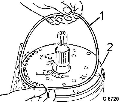
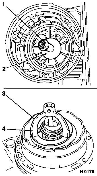
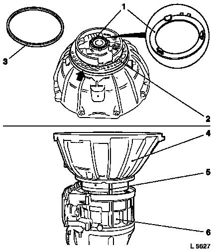
Detach seal ring (1) from intermediate casing. Seal ring is not
re-used.
Lift support plate (2) off fluid pump and remove.
|
|
|
Detach O-ring (2) from drive shaft (1). O-ring is not
re-used.
Remove fluid pump (3) from intermediate casing (5).
Detach gasket (arrow) from fluid pump. Gasket is not
re-used.
Remove thrust washer (4, optional).
|
|
|
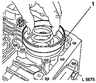
Remove thrust ring (1) for 4th gear clutch and overrunning
clutch assembly with clutch discs from intermediate casing.
|
|
|
Detach clutch discs.
Steel plates: x 4.
Lining plates: x 2.
One steel plate remains in the casing, remove this as well.
Caution
If clutch plates are not being replaced, install in original
position. See also "Technical Data" for number of steel and lining
plates.
|
|
Remove
|
Remove hollow gear from the intermediate casing.
|
|
|
Remove thrust washer (1) from intermediate casing (2).
|
|
|
Remove intermediate casing (1) with piston for 4th gear clutch,
centre support and piston for reverse clutch from transmission
casing (2).
Place KM-680-A (3) on spring set seat (5) in intermediate
casing.
Insert KM-J-23078-A (4) through KM-680-A and the bore hole in
the intermediate casing so that the thread piece protrudes at
rear.
|
|
|
Position sleeve of KM-J-23078-A (1) at centre support hub (2)
and compress KM-J-23078-A using fastening nut (3) until retaining
ring for spring set seat is free.
Remove retaining ring out of ring groove using suitable
screwdriver.
Relieve tension on KM-J-23078-A and detach. Detach KM-680-A.
Detach retaining ring (5) and spring set seat (4) with relief
springs from clutch piston (6).
Note: Relief springs
can only be replaced in assembly with spring set seat.
|
|
Remove
|
Optionally detach thrust washer (2) from centre support hub
(3).
Detach gasket (1) and seal ring (4) from intermediate casing.
Gasket and seal ring are not re-used.
Attach KM-J-23078-A to the reverse clutch.
Attach sleeve (5) at the inside of the intermediate casing to
the clutch piston.
Compress the relief springs using the fastening nut (6) until
the retaining ring is free on the rear of the intermediate
casing.
|
|
|
Turn intermediate housing upside down.
Remove retaining ring (2) from the groove with KM-396.
Relieve tension on KM-J-23078-A (1) and detach.
Detach retaining ring (5).
Detach seat (3) for relief springs and 24 relief springs from
reverse clutch.
Remove clutch piston (4) from intermediate housing.
|
|
|
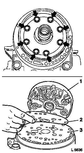
Detach 8 fastening bolts (arrows) for centre support.
Remove centre support (1), gasket (2), support plate (3) and
gasket underneath support plate. Do not reuse gaskets.
Note: Corresponding
installation position is predetermined by bore holes. Support plate
and gaskets are available as a set.
|
|
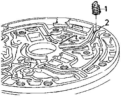
Remove
|
Remove throttle (1) from the bore (2) in the intermediate
casing. Inspect throttle, replace if necessary.
|
|
|
Remove clutch piston for 4th gear clutch out of intermediate
casing with pliers and lever.
Replace inner and outer seal ring on piston for reverse gear
clutch and 4th gear clutch. Sealing lip of seal rings always points
towards piston crown.
|
|
Remove
|
Remove assembly of 2nd and 3rd gear clutch (2) with clutch discs
(arrows) for the reverse gear from the transmission casing (1).
Detach clutch discs from assembly (3).
Damping cushion: x 1 (5)
Steel plates: x 5 (4)
Lining plates: x 4.
If clutch plates are not being replaced, install in original
position. See also "Technical Data" for number of steel and lining
plates.
|
|
|
Detach the freed axial needle bearing (1) with washer (2) from
2nd and 3rd gear clutch assembly.
Caution
Note installation position of bearing.
Remove
Remove thrust ring (3) for reverse clutch from the transmission
casing.
|
|
|
Remove planetary carrier (1) from the transmission casing.
Inspect
Check the axial needle bearing (3) and the radial needle bearing
(2) of the planetary carrier. The needle bearings are fitted
securely on the output shaft, if defective the planetary carrier
must be replaced.
|
|
Remove
|
Remove brake band drum (1) with rear sun gear (2) from
transmission housing.
|
|
|
Detach rear sun gear (2) from brake band drum (1).
|
|
|
Detach brake band at retaining lug and remove from transmission
casing.
|
|
|
Remove freed bearing (one-piece axial needle bearing with thrust
washer) from transmission casing.
Note installation position of bearing. This bearing may have
remained on the output side of the brake band drum.
|
|
|
Note: If transmission
selector lever shaft or seal ring for transmission selector lever
shaft are damaged:
Remove
In the transmission casing, detach fastening nut from the
transmission selector lever shaft.
If necessary, remove actuating rod for parking lock.
|
|
|
Remove roll pin using pliers.
For this purpose, insert nail (1) with suitable diameter into
roll pin, so that the latter is not sheared off when being pulled
out.
Use sheet metal (2) as pad to avoid damage to sealing surface of
transmission housing.
|
|
Detach shift segment from transmission selector lever shaft.
Check transmission selector lever shaft for burrs before removal
to avoid damage to seal ring.
Remove transmission selector lever shaft, if stiff press out
from inside with hammer handle. Check seal ring for wear and
damage, replace if necessary.
Install
|
Install transmission selector lever shaft. If removed: connect
actuating rod for parking lock.
Insert transmission selector lever shaft, note installation
position (groove for roll pin).
Drive in new roll pin only so far that later removal remains
possible – transmission selector lever shaft must be free to
move.
Torque
Fastening nut to shift segment – 22 Nm / 16 lbf. ft.
|
|
Remove
|
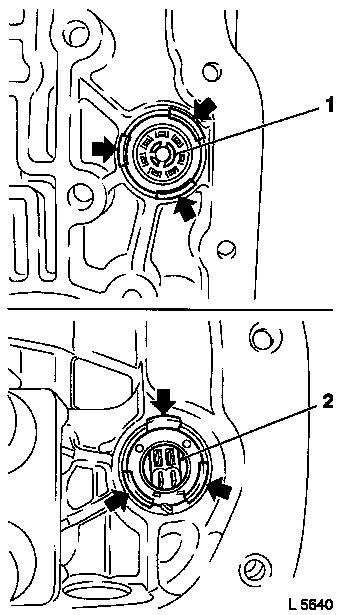
Remove connection plug (1) on main casing and connection plug
(2) on intermediate casing by pressing back the lugs (arrows) with
a screwdriver.
Inspect
Check O-rings and connection plugs for damage, replace if
necessary.
Install
Reinstall both connecting plugs without damaging O-rings.
Caution
On replacing the connecting plug on the main housing – see
operation "Adapter Piece at Main Housing, Replace".
|
|
 Assemble
|
Install brake band in transmission casing.
Install brake band, so that valve lifter of the brake band servo
piston can be installed for proper functioning.
|
|
|
Install bearing (one-piece axial needle bearing with thrust
washer).
Housing sleeve serves as guide for thrust washer and
bearing.
|
|
|
Install sun gear (2) into brake band drum (1).
|
|
|
Install brake band drum (1) with sun gear (2) in transmission
casing.
|
|
|
Note: Before further
assembly, turn transmission in adapter by 90°.
Assemble
Insert KM-689 (1) into transmission casing.
Insert relief spring for servo piston.
|
|
|
Insert servo piston assembly (1) and retaining ring into
KM-689.
Caution
If necessary, rework supports of KM-J-23075-A (3) at points
marked with arrows, so that these can be moved over KM-689 (2).
Assemble
KM-J-23075-A has an asymmetrical design. Attach KM-J-23075-A in
the position shown on transmission casing. Compress relief spring
for brake band servo piston with KM-J-23075-A until ring groove is
free.
|
|
|
Install retaining ring. Ensure it is correctly seated.
Relieve tension on KM-J-23075-A (1) and detach.
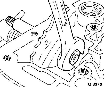
Detach KM-689 (2).
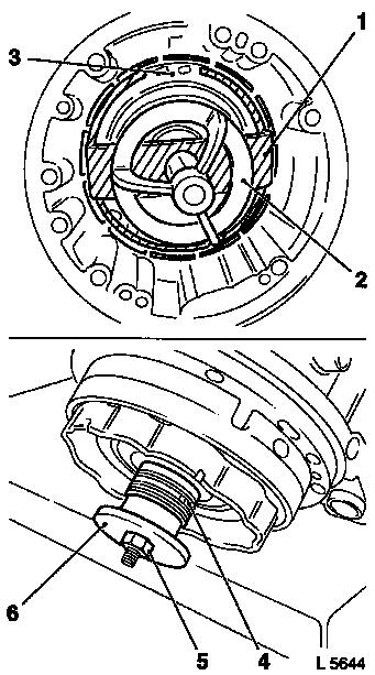
 Adjust Adjust
Adjust brake band: Release lock nut (5) at adjustment bolt.
Tighten adjustment bolt with MKM-111 (3) and MKM-J-6459-B (4) to
the prescribed torque of 5 Nm / 4 lbf. ft.
Hold sleeve and turn adjusting screw back 5 turns.
Remove insert and torque wrench.
Tighten lock nut with sleeve held in position – tightening
torque 20 Nm / 15 lbf. ft.
|
|
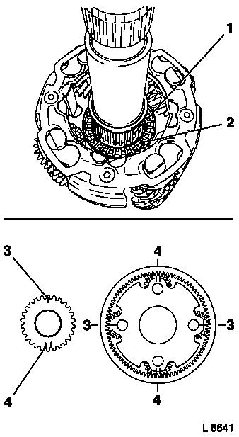
Inspect
|
Check axial needle bearing (2) and radial needle bearing (1) in
the planetary carrier for damage or wear.
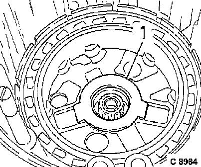
Caution
On installation, do not let planetary carrier fall into sun gear
of brake band drum, since these bearings can be damaged.
Before inserting planetary carrier
align markings on planetary gears to markings on planetary
carrier.
|
3
|
One line marking
|
|
4
|
Two line marking
|
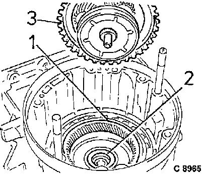
Assemble
Install planetary carrier carefully in transmission casing.
|
|
|
Place axial needle bearing (3) with washer (2) (note
installation position) onto input sun gear (1) of 3rd gear
clutch.
In order to fix, adhere bearing and washer with installation
grease.
|
|
|
Install 2nd and 3rd gear clutch assembly (1) into transmission
housing.
Caution
If any components are defective, use complete set with lining
and steel plates and thrust ring.
Insert thrust ring (2) for reverse clutch with collar side
outwards. Alternately insert steel plates (4) and lining plates
(3). Insert damping cushion (5).
|
|
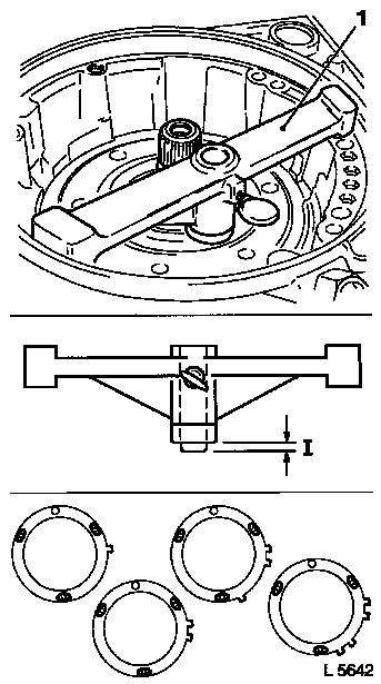
 Measure
|
Installation height of 2nd gear clutch
relative to transmission housing:
- Attach KM-J-23085-A to flange of transmission casing.
- Loosen locking screw and install inner shaft on clutch hub
contact surface.
- Tighten locking screw and remove Measuring Gauge
KM-J-23085-A.
Remove dimension "I" (illustration H
0176) at the measurement gauge (1) and select the relevant thrust
washer. The relevant washers are available via the "Aftersales"
division.
|
Transmission end play (compensation by thrust washer)
|
|
Identifier for dimension "I" of measurement operations
|
|
old version
|
new version
|
|
yellow
|
-
|
|
red
|
1 lug (1.72/1.82 mm)
|
|
black
|
2 lugs (1.91/2.01 mm)
|
|
clear, white
|
3 lugs (2.10/2.20 mm)
|
|
green
|
4 lugs (2.29/2.39 mm)
|
|
blue
|
-
|
|
|
Caution
|
Do not exceed dimension "I" with selected pressure plate, i.e.
preferably use the next smaller plate.
Assemble
Install clutch piston for 4th gear using KM-680-A (1) to hold
down spring set and using KM-837 (2) and KM-684 (3) to protect
piston seal rings.
|
|
|
Insert clutch piston (1) for 4th gear clutch into KM-684
(2).
Slide KM-684 and KM-837 onto the clutch piston to protect the
outer and inner seal ring.
Coat sealing lips of sealing rings with transmission fluid or
installation grease.
Install clutch piston with KM-680-A in intermediate casing.
Remove KM-684 and KM-837.
Install throttle (3) in bore (4) in intermediate casing. Place
lug of throttle in the fluid duct.
|
|
|
Attach KM-678 (3) to intermediate casing (2). Place support
plate (1) on intermediate casing with one gasket on each side.
Note: Support plate
and gaskets are available as a set. Installation position is
determined by bore holes.
Inspect
Check seal rings on hub of centre support for wear and lateral
play, replace if necessary.
Assemble
Attach centre support (4) loosely to intermediate casing (6
fastening bolts). Installation position is determined by the hole
pattern.
Detach KM-678, insert the remaining fastening bolts.
Tighten all fastening bolts – tightening torque 23 Nm / 17
lbf. ft.
|
|
|
Install clutch piston (2) of reverse clutch in conjunction with
Protective Sleeve KM-233-A (1) in the centre support.
Caution
Coat sealing lips of seal rings with transmission fluid or
installation grease.
Remove Protective Sleeve KM-233-A.
Assemble
Install relief springs (x 24) in clutch piston (4).
Carefully insert intermediate ring (3) for release springs and
retaining ring (5) so that release springs are correctly
positioned.
|
|
|
Attach KM-J-23087-A (3) to the reverse clutch.
Place sleeve (2) inside intermediate housing on clutch
piston.
Compress relief springs with fastening nut (1) until the groove
for retaining ring on the rear of the intermediate casing is
free.
Turn intermediate housing.
Install retaining ring (4) with KM-396 in groove.
Relieve tension on KM-J-23087-A and detach.
|
|
|
Coat selected thrust washer (3) with installation grease and
slide on hub (4) of centre support.
Attach seal ring (1).
Attach gasket (2) – installation position is determined by
the hole pattern.
Place spring set seat with relief springs (5) onto clutch piston
(7).
Insert retaining ring (6).
|
|
|
Place KM-680-A (1) on the spring set seat (3) in intermediate
casing.
Guide KM-J-23078 (2) through KM-680-A and bore hole in
intermediate casing, so that threaded piece protrudes at rear.
Attach sleeve of KM-J-23078-A (6) to hub of centre support (4)
and compress KM-J-23078-A using fastening nut (5), so that the
groove for the retaining ring of the spring set seat is free.
Install retaining ring in ring groove with suitable
screwdriver.
Relieve tension on KM-J-23078-A and detach. Remove KM-680-A.
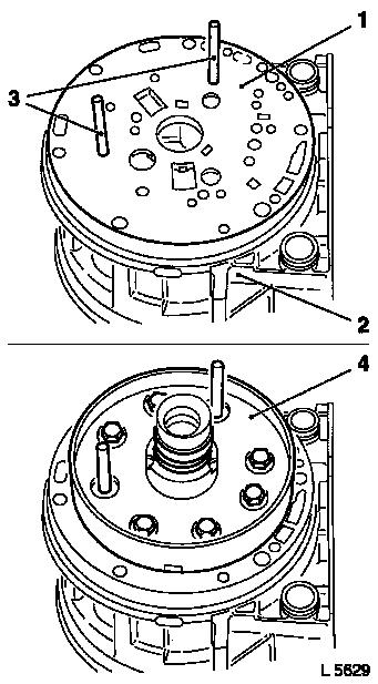
|
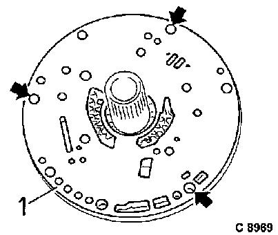
|
|
Install new O-rings (2) in transmission casing.
Install KM-675 (1) in bore holes shown in transmission
casing.
Caution
Leave KM-675 installed until converter housing is fitted.
Assemble intermediate casing (3) and transmission casing
(4).
Caution
Carefully slide intermediate casing onto KM-675 so as not to
damage the gasket.
|
|
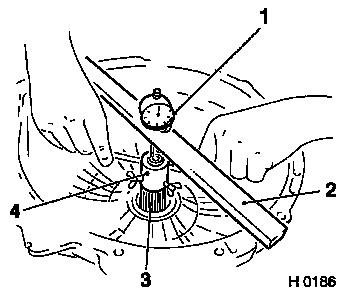
Measure
|
Measure axial play of drive shaft:
Slide KM-681-1 (3) over KM-675.
Attach KM-681-1 on intermediate casing with three fastening
bolts.
Position KM-681-2 (4) on drive shaft.
Position KM-238-2 (2) in conjunction with MKM-571-B (1) on
intermediate casing with corresponding pin as extension and set
dial gauge to "zero".
Manually load drive shaft axially at housing output in both
directions. Read off play from gauge.
Play must be between 0.36 mm (0.014") and 0.79 mm (0.031").
|
|
Assemble
|
Install thrust washer (1) with guide tabs in corresponding
recesses in the clutch piston for 4th gear.
|
|
Caution
|
If thrust bearing (2) was removed, ensure it is properly seated
– note installation position.
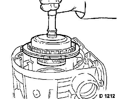
Assemble
Install hollow gear (1) and overrunning clutch assembly (3) in
the intermediate casing.
Install overrunning clutch assembly into intermediate housing by
turning slightly.
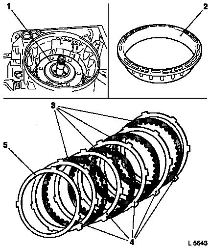
|
|
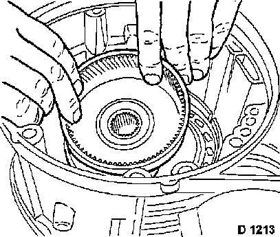
Caution
|
The lining plates must be laid in transmission fluid for about
20 minutes prior to installation.
Installation position of clutch discs and of thrust ring is
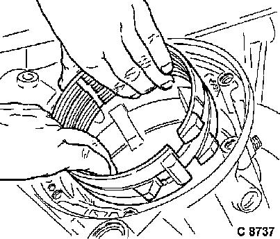
determined by guide lugs.
Assemble
Alternately install steel plates (1) and lining plates in the
intermediate casing.
Insert thrust ring (2) with recess (3) outwards.
Attach KM-J-23085-A (4) to flange of intermediate casing.
Loosen locking screw and install inner shaft on clutch hub
contact surface.
Tighten locking screw and remove Measuring Gauge
KM-J-23085-A.
|
|
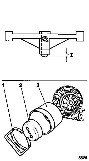
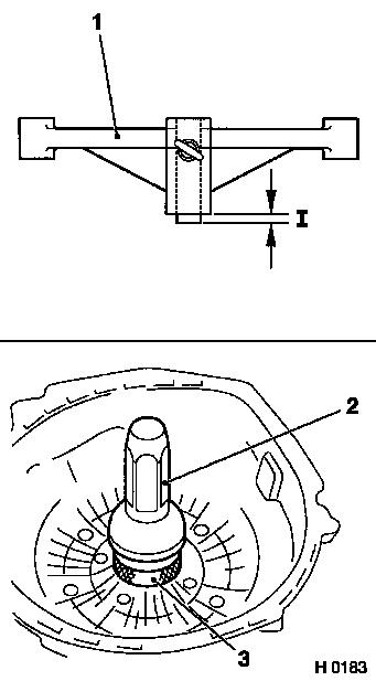
Measure
|
Remove dimension "I" (Illustration H
0183) at the measurement gauge (1) and select the relevant thrust
washer. The relevant thrust washers are available via the
"Aftersales" division.
|
Transmission end play (compensation by thrust washer)
|
|
Identifier for dimension "I" of measurement operations
|
|
old version
|
new version
|
|
yellow
|
-
|
|
red
|
1 lug (1.72/1.82 mm)
|
|
black
|
2 lugs (1.91/2.01 mm)
|
|
clear, white
|
3 lugs (2.10/2.20 mm)
|
|
green
|
4 lugs (2.29/2.39 mm)
|
|
blue
|
-
|
Do not exceed dimension "I" with the selected thrust washer,
i.e. preferably use next smaller sized washer.
Install
Install seal ring for the fluid pump in converter housing.
Attach KM-613-1 (3) and KM-J-28540 (2) and drive seal ring into
converter housing.
|
|
Assemble
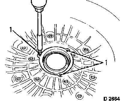
|
After installation, secure seal ring with three fastening bolts
(1).
|
|
|
Install support plate (1) onto fluid pump.
Installation position of support plate (1) is determined by bore
holes (arrows).
|
|
|
Place converter housing (2) on fluid pump. Installation position
of converter housing is determined by hole pattern of outer bolt
circle.
Insert KM-676 (1) into outer screw circle for locking. Install 5
fastening bolts of the inner screw circle and loosely tighten.
Fit KM-692 (3) up to stop on fluid pump shaft – outer part
fits into fluid pump seal ring.
Hold lower tommy bar, manually tighten upper tommy bar
(arrow).
This centralises the fluid pump with respect to the converter
housing.
Torque
Tighten 5 inner fastening bolts for fluid pump at converter
housing alternating crosswise – 20 Nm / 15 lbf. ft.
Release KM-692 at upper toggle and remove. Remove KM-676.
|
|
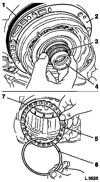
Assemble
|
Coat selected thrust washer (1) with installation grease and
attach to fluid pump hub – note installation position.
Attach gasket (2) – installation position is determined by
the hole pattern.
Attach seal ring (3) to converter housing (arrow).
Caution
Avoid damaging the gasket with KM-675 (5).
Assemble
Carefully attach converter housing (4) on intermediate casing
(6) with fluid pump installed.
|
|
|
Insert 5 fastening bolts on outer screw circle and tighten
slightly. Detach KM-675, insert remaining 2 fastening bolts and
tighten slightly.
Measure
Measure final axial play: Slide KM-682 (4) onto drive shaft and
tighten locking bolt.
Position KM-238-2 (2) in conjunction with MKM-571-B (1) and
corresponding pin as extension on converter housing and place probe
of dial gauge on face of drive shaft.
Caution
Pull drive shaft (3) with KM-682 upwards until point of contact
is noticeable. Set dial gauge to "zero". Then continue to turn
drive shaft upwards and read off the play on the dial gauge. Play
must be between 0.10 mm (0.004") and 0.69 mm (0.027").
|
|
Remove
|
Detach MKM-571-B, KM-238-2 and KM-682.
Assemble
Install new O-ring (1) on drive shaft.
|
|
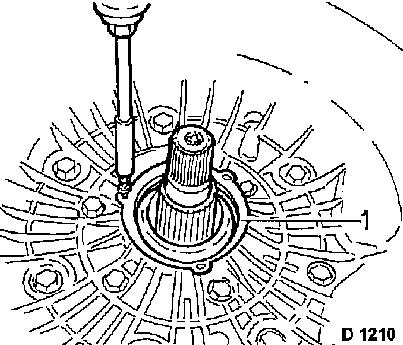
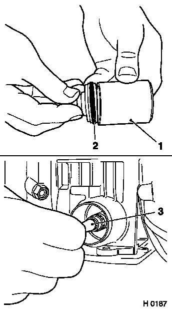
Assemble
|
Replace O-ring (2) of 3/4 accumulator piston.
Slide 3/4 accumulator piston into KM-685 (1) to protect
O-ring.
To do this, coat O-ring with transmission fluid or installation
grease.
For further assembly, turn transmission in adapter by
90°.
Insert accumulator piston in conjunction with KM-685 into
transmission casing.
Install accumulator piston with suitable pipe (3).
Remove KM-685.
|
|
|
Insert pin (2) and spring (1).
Install new seal cap (3) for accumulator piston.
|
|
|
Attach KM-686-1 (2) to the intermediate casing. The short side
of bridge points to the converter housing. Compress accumulator
spring with KM-469-14 (3) until the ring groove is free. Install
retaining ring (1). Ensure correct seating – press into ring
groove with screwdriver if necessary. Relieve tension on KM-686-1
and detach with KM-469-14 (3).
|
|
Caution
|
Before further assembly, turn transmission in adapter by
90°.
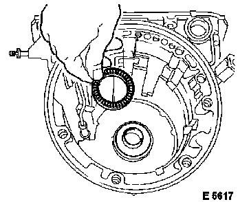
Assemble
Fit fluid reservoir (3) in the transmission casing. Installation
position is determined by the guide (2). Insert vent pipe (1) in
bore in transmission casing and fluid reservoir.
Slide parking lock gear (5) onto output shaft.
Install pulse pickup (6) of output speed sensor onto output
shaft.
Attach new gasket (4) onto transmission casing.
|
|
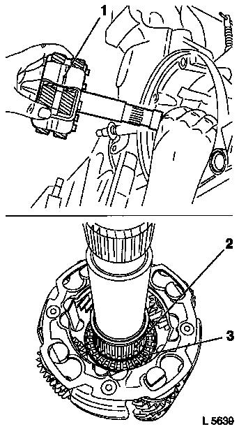
Inspect
|
Check seal ring (2), radial needle bearing (1) and liner (3) in
the extension for damage and wear, replace with new parts if
necessary.
Only required when replacing: Remove seal ring using KM-J-7004
in conjunction with KM-586.
Assemble
Install retaining spring (5) with angled end towards pawl and
pawl (4) for parking lock gear in transmission extension.
|
|
Caution
|
Actuation rod (2) for parking lock must slide in the liner.
Assemble
Position transmission extension (1) onto transmission
casing.
If fitted – attach bracket for wiring harnesses (3, 4 and
5) with fastening bolts (arrows) crosswise.
Torque
Transmission nose piece to transmission housing – 32 Nm /
23.5 lbf. ft.
|
|
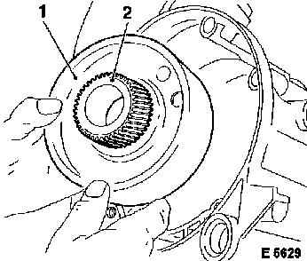
Assemble
|
Install new seal ring with KM-629-1 (1) in transmission
extension.
|
|
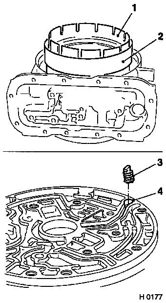
|
Insert valve ball (1) into the fluid duct of the intermediate
casing. Secure with installation grease.
Caution
The installation sequence must be observed. Gasket (2) is
provided with a slot. Gasket (4) is provided with 2 bores at the
corresponding location.
Assemble
Place gasket (2), support plate (3) and gasket (4) onto valve
body (5) of intermediate casing.
|
|
|
Place valve body assembly with gaskets and support plate (1)
onto intermediate casing. Insert 7 fastening bolts.
Torque
Valve body to intermediate housing – 20 Nm / 15 lbf.
ft.
|
|
|
Route wiring harness at the plug connection for pressure
regulator solenoid valve (1) under the retaining lug (2).
Connect wiring harness plug to pressure regulator solenoid
valves (1) and converter clutch (3).
Insert connecting plug into intermediate housing (5).
Restore plug connection (4 and 5) on the intermediate
casing.
|
|
|
Insert 2 valve balls into fluid ducts (arrows) of transmission
housing.
Caution
Use installation grease for fixing.
Assemble
Attach KM-678 (2) to transmission casing.
Put gasket (1) onto transmission housing.
|
|
|
Place valve body (1) over KM-678 (2) onto transmission
casing.
Caution
Long end of control lever points towards shift valve.
Assemble
Attach shift valve (5) with control lever (3) in valve body
assembly.
Attach control lever to shift segment (4).
|
|
|
Attach 7 fastening bolts (arrows) – tightening torque 20
Nm / 15 lbf. ft.
Detach KM-678 (1 and 2).
Insert main housing connection plug – insert new
additional support O-ring in dedicated groove.
Insert 7-pin wiring harness plug (4) at connection plug on
transmission. Route wiring harness for solenoid valves correctly
through indentations of the valve body to prevent damage when
bolting on fluid screen.
Attach detent spring (3) to transmission with fastening bolts
(arrows) – tightening torque 20 Nm / 15 lbf. ft.
|
|
|
Place wiring harness (2) on valve body assembly (4).
Attach wiring harness plug to solenoid valve for 1/2 and 3/4
shift (5).
Attach wiring harness plug to solenoid valve for 2/3 shift
(1).
Attach wiring harness plug to brake band servo solenoid valve
(3).
|
|
|
Attach brake band servo cover (1) with new gasket (4 fastening
bolts) – tightening torque 25 Nm / 18 lbf. ft.
Attach fluid screen (3) with stuck-on gasket (2) to valve body
assembly (3 fastening bolts) – tightening torque 20 Nm / 15
lbf. ft.
|
|
Caution
|
Insert fastening bolts with locking compound, if not
microencapsulated.
Torque
Attach fluid pan (1) with gasket (2) to intermediate casing (3)
(12 fastening bolts) – tightening torque 12 Nm / 9 lbf.
ft.
Caution
Insert fastening bolts with locking compound, if not
microencapsulated.
Torque
Attach fluid pan (4) with gasket (5) and fixing magnet (7) on
transmission casing (6) (16 fastening bolts) – tightening
torque 12 Nm / 9 lbf. ft.
|
|
Assemble
|
Attach output speed sensor to transmission extension (1
fastening bolt and washer) – tightening torque 12 Nm / 9 lbf.
ft.
|
|
|
Push selector lever position switch with wiring harness (1) onto
transmission selector lever shaft (2) and screw in 2 fastening
bolts – only tighten after the adjustment.
Adjust
Adjust selector lever position switch – see corresponding
operation in this group.
|
|
Assemble
|
Apply locking compound to the thread of the output shaft.
Attach output flange (2) to output shaft with fastening nut
– tightening torque 100 Nm / 74 lbf. ft.
Note: Use socket A/F
30, extra long and KM-623 (1) to counterhold.
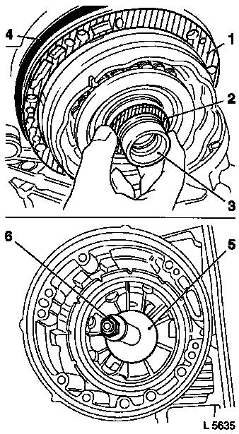
Assemble
Attach torque converter with KM-574 (3) to drive shaft.
Remove KM-574.
|
|
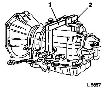
Remove
|
Detach transmission with KM-113-A (1) and KM-113-5 (2) from
KM-113-2.
Detach KM-113-A and KM-113-5.
Install
"Automatic Transmission, Remove and Install (Vehicles with
4-Cylinder Petrol Engine)", "Automatic Transmission, Remove and
Install (Vehicles with V6 Engine)", "Automatic Transmission, Remove
and Install (Vehicles with Diesel Engine)".
|
|
|
