vauxhall Workshop Repair Guides

Vauxhall Workshop Service and Repair Manuals

Connector on Intermediate Housing, Replace > < Wiring Harness for Solenoid Valves in Intermediate Housing, Replace (except Y 25 DT)

Connector on Main Housing, Replace

Caution

In vehicles with 4 cylinder OHC engine: Remove DIS ignition module – see operation "DIS Ignition Module, Remove and Install" in group "J".

Disconnect catalytic converter from front muffler, with V6 engine both (arrows).

Disconnect selector rod (3) from selector intermediate lever (1). For this, remove retaining plate (2).

Position hydraulic jack with adapter 09 00 094 and clamp plate F 09 18 021 at transmission.

Disconnect fastening bolts (4) and (6) for transmission crossmember (5) from vehicle underbody. Carefully lower transmission. Temporarily place hydraulic jack to side.

Object Number: 2392255  Size: DEFAULT

  Remove

Remove checking screw (1) and drain off transmission fluid.

Caution

Following test drive, beware of hot transmission fluid – danger of burning!

  Remove

Disconnect transmission fluid pan from main housing (16 fastening bolts) – leave 2 fastening bolts (2) screwed in 2 opposite corners.

Position hydraulic jack with adapter and clamp plate beneath transmission fluid pan – accordingly align slanting position at spindles (2) and (3). Unscrew 2 remaining fastening bolts and carefully lower transmission fluid pan – if difficult, carefully loosen fluid pan with suitable tool from main housing.

Object Number: 2392256  Size: DEFAULT

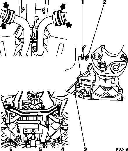
Drain and clean fluid pan. Fluid pan may be filled with hot transmission fluid – danger of burning!

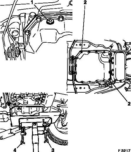
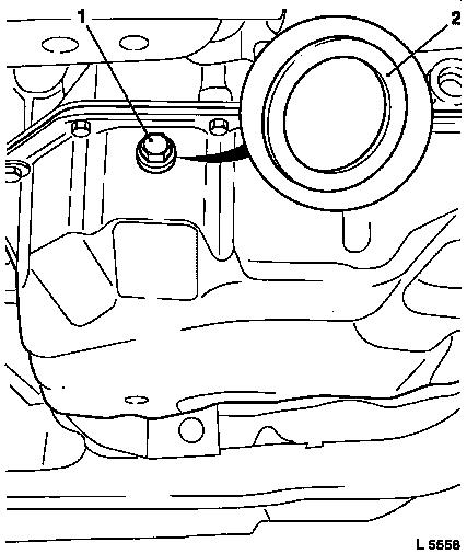
If available: Remove outer O-ring from adapter – this is no longer used.

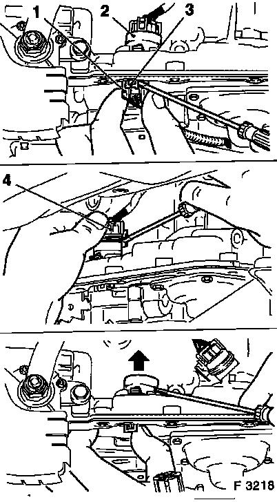
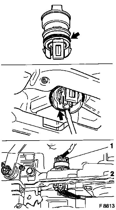
Disconnect 7-pin wiring harness plug (1) in main housing from adapter (2) – to do this, carefully push retaining ring (3) to side with small screwdriver. On disconnecting the plug connection, do not pull on wiring harness plug.

Disconnect wiring harness plug X9 (4) from adapter – to do this, unlock retaining clip (on side of housing) with small screwdriver – on disconnecting the plug connection, do not pull on wiring harness plug.

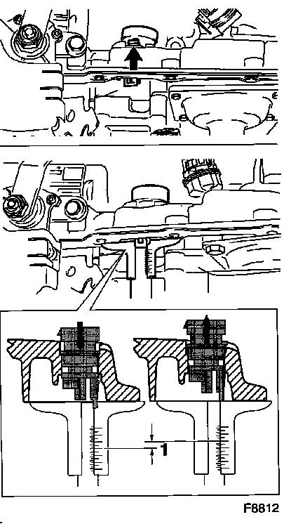
Press adapter into the bore hole in main housing by compressing the lock from inside outwards. Then press adapter out of the bore hole in main housing with screwdriver in the direction of the arrow.

Clean seat of adapter in main housing.

Object Number: 2392257  Size: DEFAULT

Note:   In transmissions up to transmission number 4 882 185 deviating tolerances between the housing bore hole and adapter may exist. In order to compensate the tolerances, the axial play between the transmission housing and the new adapter must be determined and compensated for with corresponding spacer rings. The relevant procedure is described in the following.

  Inspect

Insert new adapter in transmission housing – adapter must engage. Press adapter downwards into bore and measure gap from adapter on fluid pan surface with depth gauge. Then press adapter upwards and re-measure gap from adapter on fluid pan surface with depth gauge. The difference determined (1) gives the strength of the compensation ring which can be selected from the following table.

Axial play in mm

necessary spacer ring

0 to 1.0

without

1.01 to 1.5

96 042 161

1.51 to 2.0

96 042 162

2.01 to 2.5

96 042 163

2.51 to 3.0

96 042 164

3.01 to 3.5

96 042 165


Object Number: 2395240  Size: DEFAULT

  Install

Insert O-ring (arrow) in groove of adapter. Thinly coat O-ring with transmission fluid.

Insert adapter with O-ring into transmission housing until locks engage.

In transmissions up to transmission number 4 882 185: Install previously selected spacer ring over the locks of adapter (arrow) – ensure perfect seat on transmission housing.

Connect wiring harness plug X9 (1) to adapter from outside.

Connect wiring harness plug X9 (2) for solenoid valves from inside to outside to adapter.

Object Number: 2395241  Size: DEFAULT

Position transmission fluid pan with new seal at main housing and tighten evenly – Cut thread and insert fastening bolts with locking compound.

Torque

Attach transmission fluid pan to main casing – tightening torque 12 Nm / 9 lbf. ft.

Place hydraulic jack, KM-904 and KM-6195 at transmission.

Object Number: 2389859  Size: DEFAULT

Raise transmission with hydraulic jack. Bolt transmission crossmember to vehicle underbody, insert both bolts (arrows) with locking compound – tightening torque 45 Nm / 33 lbf. ft. Position catalytic converter (both with V6) and tighten – tightening torque 25 Nm / 18.5 lbf. ft.

Attach selector rod to selector intermediate selector lever and secure with locking plate.

Only in vehicles with 4 cylinder OHC engine: Install DIS ignition module – see operation "DIS Ignition Module, Remove and Install" in group "J".

Object Number: 2388085  Size: DEFAULT

Fill in transmission fluid up to lower edge of checking/filler opening.

Torque

Insert checking screw (1) with old seal (2) in checking/filler aperture temporarily and tighten – 33 Nm / 24.5 lbf. ft. (inner hex screws), 30 to 40 Nm / 22 to 29.5 lbf. ft. (external hex screws).

Check transmission fluid level and correct – see operation "Transmission Fluid Level, Check and Correct".

Object Number: 2417614  Size: DEFAULT


Related Literature Units
-
-
-
-

Connector on Intermediate Housing, Replace > < Wiring Harness for Solenoid Valves in Intermediate Housing, Replace (except Y 25 DT)