Engine, Lock at 1st Cylinder TDC (Timing, Check)
 Remove, Disconnect Remove, Disconnect For X 20 DTH with air conditioning: Detach relay box from air cleaner housing and place to one side. Remove air cleaner housing with hot film mass air flow meter and air intake hose - see illustration "Air Cleaner Housing, Air Duct". Remove cylinder head cover - see operation "Cylinder Head Cover, Remove and Install". Remove vacuum pump from cylinder head and lay aside to rear - see operation "Vacuum Pump, Remove and Install". Remove ribbed V-belt tensioner - see operation "Ribbed V-belt Tensioner Assembly, Remove and Install". Remove front exhaust pipe. Remove fastening nut from engine damping block bracket (1). Attach engine to Engine Bridge MKM-883-1 (2) and raise engine as far right as possible in direction of travel thereby ensuring that no components are damaged. | 
|
Remove, Disconnect Remove fastening bolts from timing case cover (1) and carefully separate timing case cover from timing case with a wide, flat spatula (2).
 Important! Important! The timing case cover must not be levered off or separated from the timing case by force; this would lead to permanent deformity and leaks. | 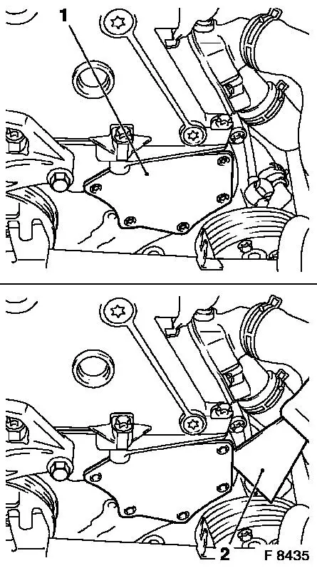
|
 Adjust Adjust At the torsional vibration damper fastening bolt, turn crankshaft slowly and smoothly in direction of engine rotation until just in front of 1st cylinder ign. TDC - mark (3) on torsional vibration damper is located just in front of timing case lug (2).
 Inspect Inspect In this position, the cams (1) of the 1st cylinder are just before TDC (both cams point upwards). | 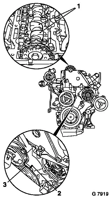
|
Remove, Disconnect Remove crankshaft pulse pick-up (1) with O-ring from cylinder block.
 Install, Connect Install, Connect Insert Crankshaft Lock Pin KM-929 (2) in aperture for crankshaft pulse pick-up and simultaneously slowly turn the crankshaft in engine rotational direction at the fastening bolt of the torsional vibration damper until the crankshaft lock pin engages to stop in the cylinder block or crank web.
Inspect In this position, the marks (3) must be aligned. | 
|
Inspect Arrow (1) on Simplex injection pump gear must be aligned with the recess in injection pump flange and retaining bore (2) in injection pump.
Install, Connect Insert Injection Pump Lock Pin KM-927 (3) in lock bore of fuel injection pump. Notice: If the injection pump lock pin could not be inserted in the injection pump lock bore, then a basic adjustment must be performed - see operation "Timing, Adjust". | 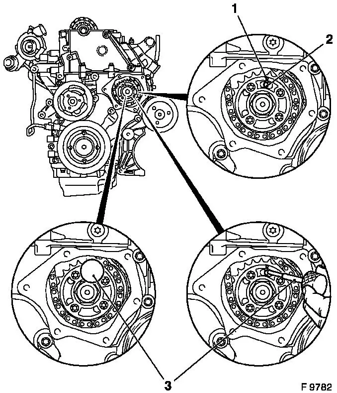
|
Install, Connect Apply Test Gauge KM-932 (3) to cylinder head - pin (2) must engage in bore (1) of camshaft. Notice: If it is not possible to insert the reference gauge, a basic adjustment must be performed - see operation "Timing, Adjust". | 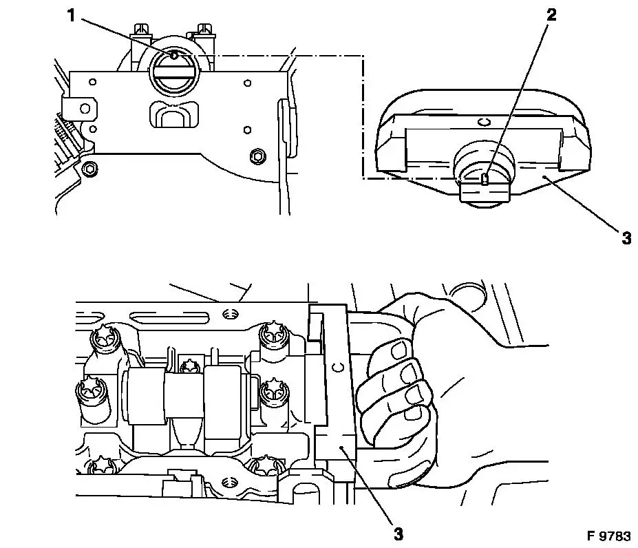
|
Remove, Disconnect Remove all locking tools.
 Clean Clean Clean sealing surfaces on timing case cover and on timing case - cover timing case aperture with lint-free cloth.
Install, Connect Apply an approx. 2 mm (Dimension I) thick bead of silicone sealing compound (grey) to timing case cover. Attach timing case cover to timing case with new fastening bolts - secure using 2 threaded bolts (M6) - tightening torque 6 Nm / 4.5 lbf. ft.
Important! The application of silicone sealing compound (grey), installation of timing case cover and tightening to torque must be performed within 10 minutes. | 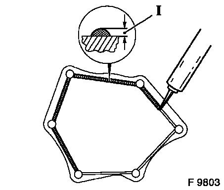
|
Install, Connect Attach crankshaft pulse pick-up to cylinder block with new seal ring - tightening torque 8 Nm / 6 lbf. ft. Lower engine using engine bridge and attach engine damping block bracket to engine damping block - tightening torque 45 Nm / 33 lbf. ft. Connect front exhaust pipe to return manifold with new gasket and new fastening nuts - tightening torque 20 Nm / 15 lbf. ft. Connect front exhaust pipe to muffler - tightening torque 12 Nm / 9 lbf. ft. Install ribbed V-belt tensioner - see operation "Ribbed V-belt Tensioner Assembly, Remove and Install". Install vacuum pump - see operation "Vacuum Pump, Remove and Install". Install cylinder head cover - see operation "Cylinder Head Cover, Remove and Install".
Notice: Before assembling components of the intake system (hoses, connections, etc.), they must be cleaned of any possible contamination (grease, oil, etc.). When tightening the hose clamps, be sure to observe exactly the tightening torque of 3.5 Nm / 2.6 lbf. ft.
Important! It is only ensured that the intake system is free of leaks, thus ensuring operational safety of the engine, if the hose clamps are tightened correctly to the prescribed tightening torque.
Install, Connect Install air cleaner housing with hot film mass air flow meter and air intake hose - see illustration "Air Cleaner Housing, Air Duct". For X 20 DTH with air conditioning: Attach relay box to air cleaner housing.
|
