Cylinder Head, Remove and Install
 Important! Important! Remove cylinder head from cold engine only (room temperature).
 Adjust Adjust Lock engine at 1st cylinder TDC - see operation "Engine, Lock at 1st Cylinder TDC (Timing, Check)".
 Install, Connect Install, Connect Move engine as far as possible to the right (in direction of travel) using Engine Bridge MKM-883-1 - thereby ensuring that no components are damaged.
 Remove, Disconnect Remove, Disconnect Detach engine damping block bracket (1) from engine damping block adapter (2) and detach engine damping block adapter from timing case. Lower engine using Engine Bridge MKM-883-1 until it is horizontal. | 
|
Important! To remove timing case, coolant pump must be removed with engine inclined - see operation "Coolant Pump, Remove and Install".
Remove, Disconnect Unclip hydraulic lines (1) from bracket and carefully push away from front axle body. Attach Engine Mount KM-6173 (4) to front axle body - screw up support bolt (3) until it lies flush against cylinder block mount (2). Lower engine and remove Engine Bridge MKM-883-1. | 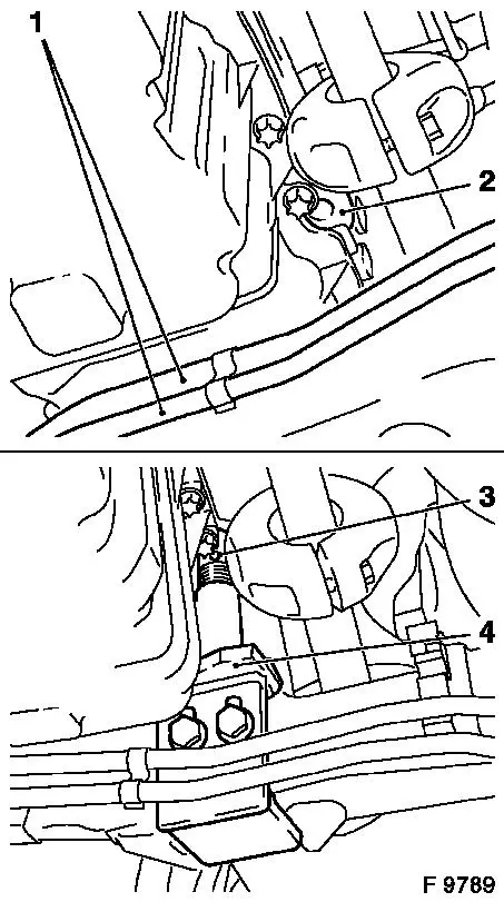
|
Remove, Disconnect Remove lower coolant hose from radiator. Collect escaping coolant. Detach coolant hose (1) from cylinder head and lay aside. Detach vacuum hose (2) from exhaust gas recirculation valve. As of MY '98: Detach power steering pump fluid reservoir from air cleaner housing and place to one side. Detach fuel lines (3) and oil leak line from fuel injection pump and remove towards rear. Detach thermostat housing (4) from cylinder head and with coolant hoses attach to a suitable place. Detach injection lines (5) from injection pump and from injector nozzle traverse - note installation position of fastening clips. Detach vacuum hose (6) from switchover valve vacuum unit. Disconnect wiring harness plug bracket for crankshaft pulse pick-up (7) from upper part of intake manifold. | 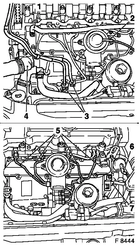
|
Remove, Disconnect Up to MY '98: Detach conduction bridges (4) from glow plugs together with wiring connections. As of MY '98: Detach wiring trough for glow plugs - release connection plug with KM-717 and remove. Remove central heat shield (2), left heat shield (1), right heat shield (3) and lower heat shield (starter) (5). Remove alternator wiring trough from cylinder block (3 fastening bolts) and carefully push away downwards. Detach turbocharger oil return line (6) and turbocharger oil feed line (8) from cylinder block -collect escaping engine oil. Remove exhaust manifold support (7) from exhaust manifold and release from cylinder block - swing support to side. | 
|
Remove, Disconnect Detach vacuum hose (1) from wastegate unit. Detach coolant hose (2) from alternator bracket (coolant flange). Remove upper alternator fastening bolt (3) and only release lower alternator fastening bolt (4) - swing alternator to rear. Remove simplex chain tensioner (5) - note installation position. Heat fastening bolts (6) intensively with hot air blower and remove.
Important! Use sheet metal plate or suitable heat shielding to avoid damaging the guide rails.
Remove, Disconnect Remove guide rail for Simplex timing chain upwards - note installation position. | 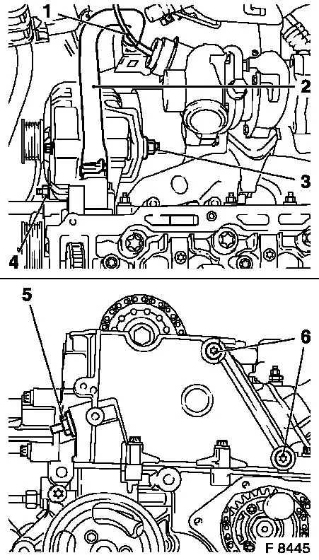
|
Remove, Disconnect Remove Test Gauge KM-932 from cylinder head and Injection Pump Lock Pin KM-927 from lock bore. Detach camshaft sprocket from camshaft and remove from simplex timing chain - counterhold with open-ended wrench on hex of camshaft. Lay simplex timing chain aside in channel. Remove fastening bolts (arrows) from cylinder head - note different bolt lengths. First loosen cylinder head bolts in the illustrated sequence 1/4 then 1/2 turn and remove. | 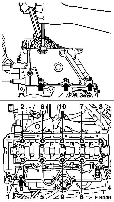
|
Remove, Disconnect Remove cylinder head.
Important! Lay cylinder head aside on wooden blocks to avoid damaging the injection nozzles, glow plugs and valves.
 Clean Clean Remove gasket remnants and clean sealing surfaces. Notice: If the cylinder head is to be checked or modified, all the outer attaching parts must be removed from the cylinder head.
 Inspect Inspect Check cylinder head and cylinder block for plane surfaces - see operations "Cylinder Head, Check for Plane Surface" and "Cylinder Block, Check for Plane Surface". Measure the piston projection using Measurement Bridge KM-301 and Dial Gauge KM-571-B. Then select the corresponding cylinder head gasket.
|
Piston projection |
Thickness of cylinder head gasket |
Code |
|
0.40 - 0.50 mm |
1.2 mm |
none |
|
0.51 - 0.60 mm |
1.3 mm |
1 notch |
|
0.61 - 0.70 mm |
1.4 mm |
2 notches |
The identification (notch) is located in position (1).
Important! For some engines in production, the cylinder head gasket is inserted with sealing compound in area of timing case. However, under all circumstances, the new cylinder head gasket must be installed dry even if the old gasket was inserted with sealing compound.
Install, Connect Place new cylinder head gasket on cylinder block. | 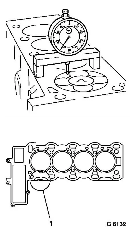
|
Install, Connect Apply Test Gauge KM-932 (3) to cylinder head - pin (2) must engage in bore (1) of camshaft. | 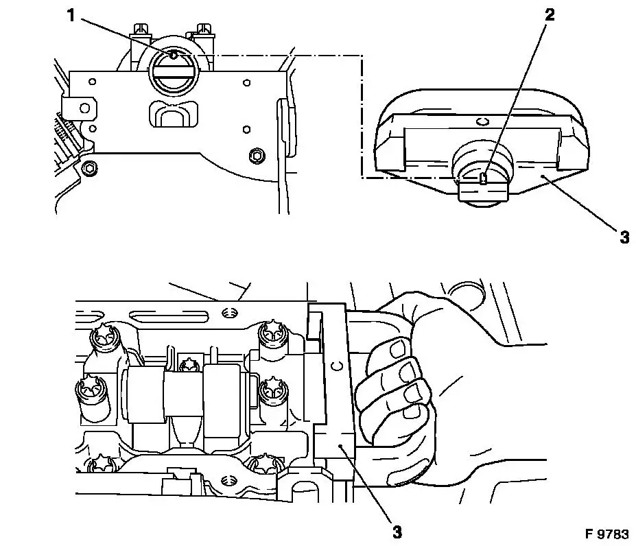
|
Install, Connect Attach cylinder head to cylinder block with new fastening bolts - note Simplex timing chain. Tighten fastening bolts in order shown with KM-470-B - tightening torque 25 Nm / 18 lbf. ft. + 65 ° + 65 ° + 65 ° + 65 ° + 15 ° 1) . Fasten cylinder head to timing case or cylinder block with fastening bolts - tightening torque 20 Nm / 15 lbf. ft. + 30 ° + 5 ° . | 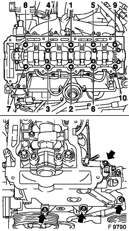
|
1) Use new fastening bolts.
Install, Connect Guide simplex timing chain upwards through channel and insert camshaft sprocket in simplex timing chain. Attach camshaft sprocket with new fastening bolt to camshaft and tighten by hand.
Important! Ensure that camshaft sprocket is seated squarely on camshaft - camshaft sprocket must sit flat against camshaft.
Install, Connect Insert and attach Simplex timing chain guide rail (1) with new fastening bolts (2), clean thread beforehand - ensure correct installation position - tightening torque 8 Nm / 6 lbf. ft. | 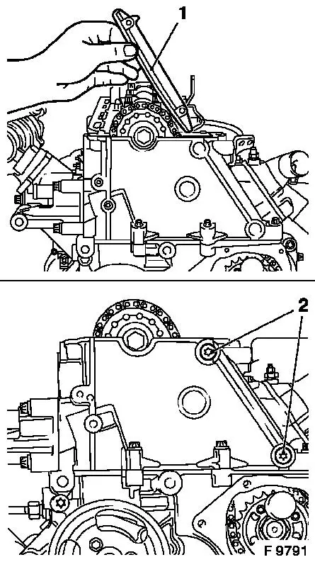
|
Inspect Arrow (1) on Simplex injection pump gear must be aligned with the recess in injection pump flange and retaining bore (2) in injection pump.
Install, Connect Insert Injection Pump Lock Pin KM-927 (3) in lock bore of fuel injection pump. | 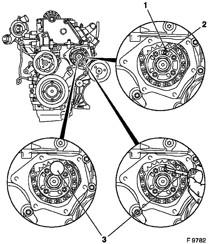
|
Install, Connect Insert carrier (1) of Adjuster KM-933 (4) vertically into camshaft sprocket. Install Adjuster KM-933 on cylinder head.
Adjust Use handle (2) to exert slight pressure on the carrier in the direction of arrow (counter engine rotational direction) and fix in place with holder bolt (3).
Important! Removal and installation of Retaining Pin KM-927 for fuel injection pump must be possible under suction. If this is not possible, the pressure on the adapter plate must be slightly reduced using the adjustment screw (3).
Install, Connect Fasten camshaft sprocket to camshaft - tightening torque 90 Nm / 66 lbf. ft. + 60 ° + 30 ° . | 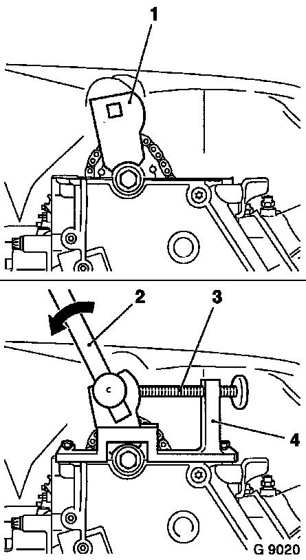
|
Install, Connect Insert simplex chain tensioner (4) in cylinder head - closed side of chain tensioner must face tension rail. Install closure bolt (2) with new seal ring (3) - tightening torque 60 Nm / 44 lbf. ft.
Important! When installing a new Simplex chain tensioner, chain tensioner must be released by means of release bolt (1) after assembly. Push in release bolt with hammer handle until click is audible. It must be possible to push in release bolt up to stop with thumb and for it to slide back to its original position automatically - the release bolt can no longer be pushed in once the oil pressure has built up. | 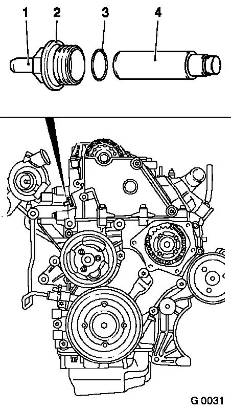
|
Remove, Disconnect Remove all locking and adjusting tools.
Adjust At the torsional vibration damper fastening bolt, turn crankshaft slowly and smoothly for two rotations (approx. 720 ° ) in direction of engine rotation until just in front of 1st cylinder ign. TDC - mark (3) on torsional vibration damper is located just in front of timing case lug (2).
Inspect In this position, the cams (1) of the 1st cylinder are just before TDC (both cams point upwards). | 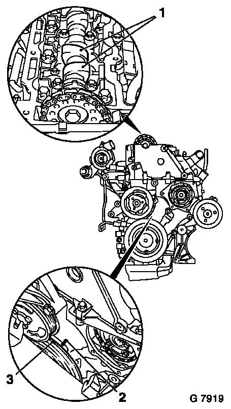
|
Install, Connect Insert Crankshaft Retaining Pin KM-929 (1) in crankshaft pulse pick-up aperture and simultaneously continue turning crankshaft slowly and smoothly in direction of engine rotation using fastening bolt for torsional vibration damper so that crankshaft retaining pin engages to the stop in cylinder block or crank web.
Inspect In this position, the marks (2) must be aligned. | 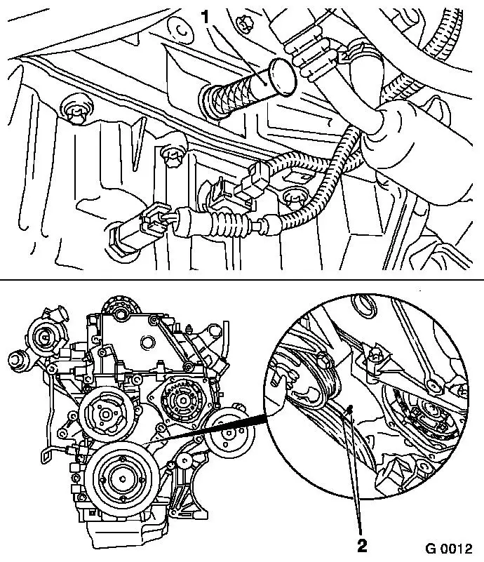
|
Inspect Arrow (1) on Simplex injection pump gear must be aligned with the recess in injection pump flange and retaining bore (2) in injection pump.
Install, Connect Insert Injection Pump Lock Pin KM-927 (3) in lock bore of fuel injection pump. |
|
Install, Connect Apply Test Gauge KM-932 (3) to cylinder head - pin (2) must engage in bore (1) of camshaft. |
|
Install, Connect Attach alternator to alternator bracket (coolant flange) - tightening torque 35 Nm / 26 lbf. ft. Attach coolant hose to alternator bracket (coolant flange) - ensure correct seating. Connect vacuum hose to waste gate unit. Attach exhaust manifold support to cylinder block and exhaust manifold - tightening torque 25 Nm / 18 lbf. ft. Attach turbocharger oil feed line and turbocharger oil return line to cylinder block - tightening torque 20 Nm / 15 lbf. ft. Attach alternator wiring trough to cylinder block (3 fastening bolts). Install/ attach all heat shields. Up to MY '98: Attach conduction bridges to glow plugs together with wiring connections. As of MY '98: Attach rear wiring harness trough and wiring harness plug for glow plugs. Attach wiring harness plug bracket for crankshaft pulse pick-up to lower part of intake manifold. Connect vacuum hose to switchover valves vacuum unit.
Install, Connect Attach injection lines to fuel injection pump without tension and to injection nozzle traverse - tightening torque 30 Nm / 22 lbf. ft. Attach fastening clips to injection lines - note installation position. Attach thermostat housing to cylinder head with new gasket - tightening torque 8 Nm / 6 lbf. ft. Attach fuel lines (with new seal rings) and oil leak lines to fuel injection pump - tightening torque 15 Nm / 11 lbf. ft. As of MY '98: Attach power steering pump fluid reservoir to fan housing. Attach vacuum hose to exhaust gas recirculation valve. Attach compensation tank coolant hose to cylinder head. Install lower coolant hose on radiator. Attach engine to Engine Bridge MKM-883-1 and raise engine as far right as possible - ensure no components are damaged. Detach Engine Mount KM-6173 from front axle body and clip hydraulic lines into retainers on front axle body.
Important! Bleed fuel system with KM-948 once it has been opened.
Remove, Disconnect Remove all locking tools.
Clean Clean sealing surfaces on timing case cover and timing case - cover aperture in timing case with lint-free cloth.
Install, Connect Apply an approx. 2 mm (Dimension I) thick bead of silicone sealing compound (grey) to timing case cover.
Important! The application of silicone sealing compound (grey), installation of timing case cover and tightening to torque must be performed within 10 minutes.
Install, Connect Attach timing case cover to timing case with new fastening bolts - secure using 2 threaded bolts (M6) - tightening torque 6 Nm / 4.5 lbf. ft. | 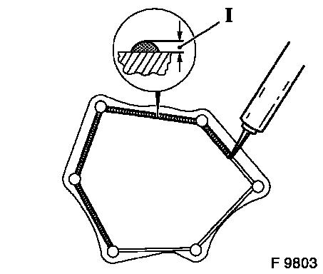
|
Install, Connect Attach engine damping block adapter to timing case - tightening torque 60 Nm / 44 lbf. ft. Attach engine damping block bracket to engine damping block adapter - tightening torque 45 Nm / 33 lbf. ft. Lower engine using engine bridge and attach engine damping block bracket to engine damping block - tightening torque 45 Nm / 33 lbf. ft. Attach crankshaft pulse pick-up to cylinder block with new seal ring - tightening torque 8 Nm / 6 lbf. ft. Connect front exhaust pipe to return manifold with new gasket and new fastening nuts - tightening torque 20 Nm / 15 lbf. ft. Connect front exhaust pipe to muffler - tightening torque 12 Nm / 9 lbf. ft. Install ribbed V-belt tensioner - see operation "Ribbed V-belt Tensioner Assembly, Remove and Install". Install vacuum pump - see operation "Vacuum Pump, Remove and Install". Install cylinder head cover - see operation "Cylinder Head Cover, Remove and Install".
Notice: Before assembling components of the intake system (hoses, connections, etc.), they must be cleaned of any possible contamination (grease, oil, etc.). When tightening the hose clamps, be sure to observe exactly the tightening torque of 3.5 Nm / 2.6 lbf. ft.
Important! It is only ensured that the intake system is free of leaks, thus ensuring operational safety of the engine, if the hose clamps are tightened correctly to the prescribed tightening torque.
Install, Connect Install air cleaner housing with hot film mass air flow meter and air intake hose - see illustration "Air Cleaner Housing, Air Duct". Top up cooling system - see operations "Cooling System, Top up and Bleed" and "Cooling System, Check for Leaks".
|
