Steering Column Assembly (Height-Adjustable), Disassemble and Assemble
 Remove, Disconnect Remove, Disconnect Remove steering column assembly - see operation "Steering Column Assembly, Remove and Install". Compress pressure spring with KM-583-A (1) and KM-J-23653-A (2). Remove retaining ring (3) using screwdriver and long-nosed pliers. Remove depressor (4), pressure spring (5), pressure ring (6) and bearing ring (7). Remove pressure spring (8) for height adjustment using KM-584 (9). | 
|
Remove, Disconnect Pull both fulcrum bearing pins (2) out of bearing housing using KM-585 (1). Remove bearing housing - release steering wheel lock if necessary.
 Disassemble Disassemble If necessary, drill out both shear bolts (3) for steering and ignition lock housing with drill bit Ø 4.5 mm/0.18 in. and remove with commercially available screwdriver. Remove steering and ignition lock housing. The bearing housing is available only as an assembly together with both ball bearings.
 Important! Important! To prevent improper assembly (180 ° twist), mark notch for steering lock (4) upper part of steering shaft (5) and lower part of steering shaft (6) for correct positioning before disassembly. Mark any new parts to correspond to the markings of parts replaced. | 
|
Disassemble When replacing bearing housing, bearing race (1) must be replaced. Disassemble universal joint (2) of steering shaft. If necessary replace damaged parts.
 Assemble Assemble Assemble universal joint and install in steering shaft. For this, the spring (3) must be seated in the recess (4) in each half of joint. If removed, press on new bearing race (1). | 
|
Disassemble Drive out lower steering shaft bearing (1) downwards (arrow).
Assemble Install lower steering shaft bearing. If removed, bolt on new casing for steering and ignition lock using shear bolts. Use new bolts (not micro-encapsulated) with Screw Locking Compound (red) 15 10 181 (90 542 117). Insert steering shaft into steering column. Install bearing housing with both fulcrum bearing pins (2). Caulk at 3 points around circumference of each (3). | 
|
Assemble Install pressure spring (2) for height adjustment using KM-584 (1). Install bearing race (6), pressure ring (5), pressure spring (4), and depressor (3) onto steering shaft and install retaining ring with KM-583-A and KM-J-23653-A.
Important! When replacing bearing housing with both ball bearings, gap (7) between housing and two stop buffers in uppermost steering wheel lock position must be checked. Compensate differences with new stop buffers. The parts must exactly engage without steering wheel being able to move any further.
 Install, Connect Install, Connect Install steering column assembly - see operation "Steering Column Assembly, Remove and Install". | 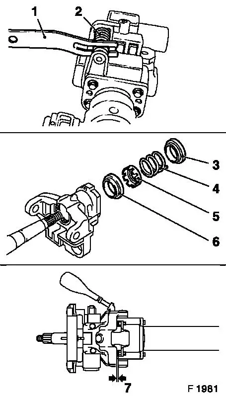
|
|
