volkswagen Workshop Repair Guides

Volkswagen Workshop Service and Repair Manuals

Removing and installing compressor bracket -up to model year 1977- > < Removing and installing controls complete
Heating, Air conditioner
Air conditioner - repairs
Combined air conditioner -from model year 1980-
 
U87-0015

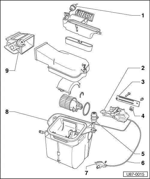
Repairs to the combined air conditioner/heater system which require no special equipment -from model year 1980-

From Chassis Nos.:


16A 0 000 001


Jetta

17A 3 000 001

Golf

53A 2 000 001

Scirocco

Due to the introduction of new controls for the air conditioner and a new switch for the fresh air blower, the additional current flow diagram and the vacuum hose connection layout have change. In conjunction with this, so have the fault finding instructions.

  • Vacuum unit for air distribution housing
    • ◆ connection layout
    • ◆ checking => page 87-102
 
U87-0015
  • Air conditioner controls complete
    • ◆ removing and installing => Figs.1 , 4
    • ◆ servicing => page 87-59
    • ◆ checking => page 87-102
    • ◆ connection layout => page 87-83
  • Air conditioner trim
  • Switch for fresh air blower, air conditioner
  • Double vacuum unit
    • ◆ connection layout => page 87-83
    • ◆ checking => page 87-102
  • Control valve cable
    • ◆ adjusting =>Figs. 2 and 3
  • Control valve
  • Feeler pipe
  • Flap box vacuum unit
    • ◆ connection layout => page 87-83
    • ◆ checking => page 87-102
 
U87-0016

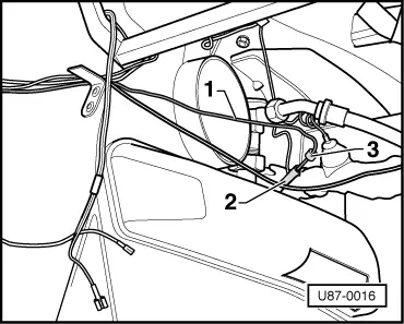
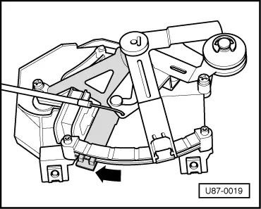
→ Fig.1     Removing feeler pipe

  • ‒ Pull the feeler pipe - 1 - out of the copper pipe - 2 - on the evaporator. Insertion depth marking - 3 -.

Note:

Do not kink the feeler pipe

 
U87-0017

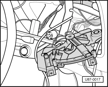
→ Fig.2     Removing air conditioner controls

  • ‒ Remove instrument panel insert.
  • ‒ Pull off the multi-point connector, control valve cable and vacuum hoses.
  • ‒ Take out controls complete with feeler pipe.
 
U87-0018

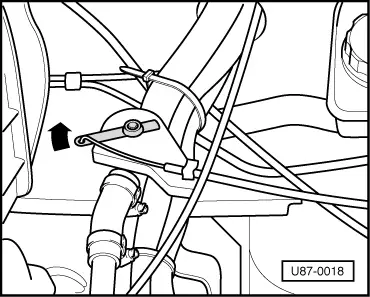
→ Fig.3     Adjusting control valve cable

  • ‒ Press the control valve lever in the direction of the arrow as for as it will go.
 
U87-0019

→ Fig.4     Adjusting control valve cable

  • ‒ Push the lower control lever as far as it will go in the direction of the arrow and attach cable.
  • ‒ Connect vacuum hose as per connection layout => page 87-83 , and plug in multipoint plug.
  • ‒ Push the feeler pipe 180 mm (up to the marking) into the evaporator copper pipe.

Note:

If the feeler pipe has become kinked, renew temperature switch.

Removing and installing compressor bracket -up to model year 1977- > < Removing and installing controls complete