volkswagen Workshop Repair Guides

Volkswagen Workshop Service and Repair Manuals

Vacuum hose > < Additional current flow diagramm -from model year 1980-
Heating, Air conditioner
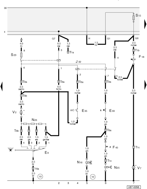
Current flow diagramm
Additional current flow diagramm -from model year 1981-
 
U87-0056

From Chassis Nos.:


16B 000 001


Jetta

17B 000 001

Golf

53B 000 001

Scirocco

Designation:

in current track:

A - to Battery

1

E9 - A/C fresh air fan switch

1

E33 - Temperature switch, lower lever

6

E35 - Air conditioner switch (Micro switch) upper level

4

F18 - Coolant fan thermoswitch

7

F45 - A/C thermoswitch (in vehicles with Diesel engine

6

 
U87-0056

J32 - A/C relay, in additional fuse holder

1 - 6

N16 - Two-way valve, note Part No. (not on vehicles with Diesel engine or TCI)

5

N23 - Fresh air blower series resistance (near fresh air fan)

1

N25 - Solenoid clutch

6

S15 - Fuse in fuse box (16 Amp.)

7

S23 - Separate fuse for A/C (25 Amp.) on A/C relay

1

T1a - Connector single, free for options, on fuse box

T1b - Connector single, on left of engine compartment

T1c - Connector single, on left of engine compartment

 
U87-0056

T6a - Connector 6 pin, behind dash

T6b - Connector 6 pin, behind dash

V2 - Fresh air fan for A/C

1

V7 - Coolant fan

7

10 - Earth point on steering column support

Wire colors:

    • ◆ ws - white
    • ◆ sw - black
    • ◆ ro - red
    • ◆ br - brown
    • ◆ gn - green
    • ◆ ge - yellow
    • ◆ gr - grey
    • ◆ bl - blue

Vacuum hose > < Additional current flow diagramm -from model year 1980-