volkswagen Workshop Repair Guides

Volkswagen Workshop Service and Repair Manuals

Adjusting input shaft > < Additionally securing magnet in clutch housing with sealing compound
4 Speed Manual Gearbox 020
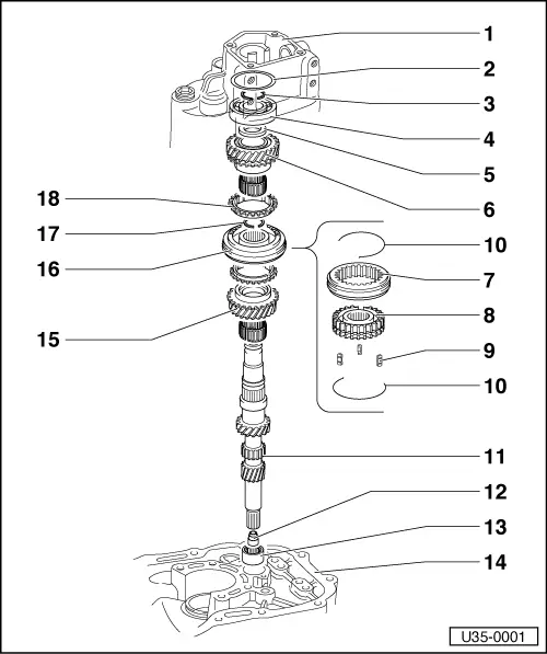
Dismantling and assembling input shaft
 
U35-0001

Note:

When installing new gears, see Technical Data =>page 00-3

  • Gearbox housing
  • Shim
    • ◆ For drive shaft measuring =>page 35-20
  • Circlip
    • Fit new, do not overstretch, must seat properly in groove.
  • Ball bearing
    • ◆ Pres off =>Fig. 1
    • ◆ Press into gearbox housing
      watch position =>Fig. 16
    • ◆ Mod. =>Fig. 17
 
U35-0001
  • Thrust washer
    • (up to 18 06 5)
    • must fit tightly
    • ◆ If replaced: Adjust drive shaft
      =>page 35-20
    • ◆ Pressing off =>Fig. 2
    • ◆ Pressing on =>Fig. 15
    • ◆ Mod. =>Fig. 17
  • 4th speed gear
    • ◆ Replace pair only.
  • Sleeve
  • Hub
  • Locking key
  • Spring
    • Wire dia.1.6 mm
    • From 28 09 6:
    • 1.4 mm dia. (improves shifting) can be installed in all 020 gearboxes.
 
U35-0001
  • Input shaft
    • ◆ Adjust if replaced =>page 35-20
  • Bush/seal for clutch push rod
    • Can be replaced with gearbox out (not dismantled) by removing cover for clutch controls, release shaft, release bearing and push rod
    • ◆ Knocking out =>Fig. 4
    • ◆ Pressing in =>Fig. 6
    • ◆ Mod. =>Fig. 7 - 10
  • Needle bearing for input shaft
    • ◆ Pulling out =>Fig. 18
    • ◆ Knocking in =>Fig. 19
  • Bearing housing
  • 3rd speed gear
    • ◆ Replace pair only
 
U35-0001
  • Sleeve/hub for 3rd/4th gear
    • ◆ Pressing off =>Fig. 3
    • ◆ Assembling =>Fig. 11 and 12
    • ◆ Watch position when pressing on
      =>Fig.14
    • ◆ Mod. =>Fig.13
  • Circlip
    • ◆ Fit new, do not overstretch, must seat properly in groove.
  • Synchronizer ring for 3rd/4th gear
    • ◆ Check for wear =>Fig.5
 
U35-0002

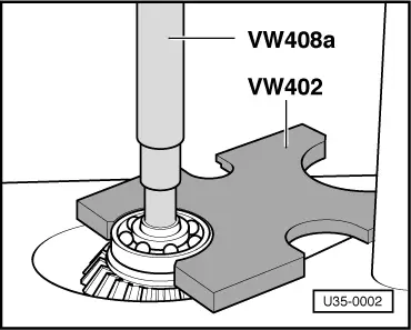
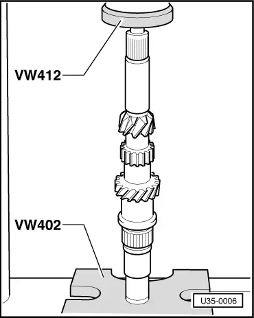
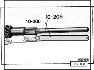
→ Fig.1     Pressing ball bearing off

 
U35-0003

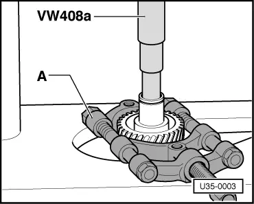
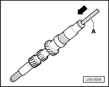
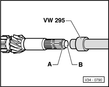
→ Fig.2     Pressing 4th speed gear and thrust washer off

A - Separating appliance
12 - 75 mm, Kukko 17/1.

  • Only up to 18 06 5
 
U35-0004

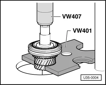
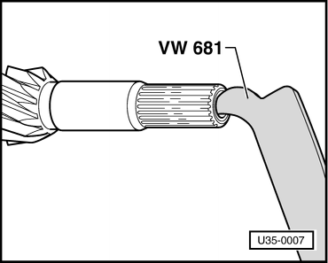
→ Fig.3     Pressing off sleeve/hub with 3rd speed gear

 
U35-0005

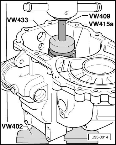
→ Fig.4     Knocking out bush and seal for clutch push rod

A = 10 mm such as an old pump shaft from automatic box.

 
V35-0975

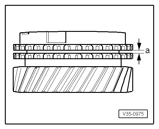
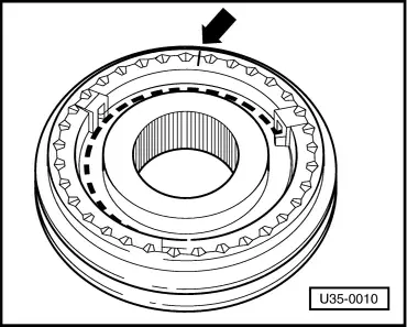
→ Fig.5     Checking synchronizer rings

  • ‒ Press synchro ring on to gear cone and measure gap "a" with feelers.

Gap "a"

New

Wear limit

3rd speed

1.15 - 1.75 mm

0.5 mm

4th speed

1.3 - 1.9 mm

0.5 mm

 
U35-0006

→ Fig.6     Pressing in bush and seal for clutch push rod

(must be flush)

Mod:

 
V35-0670

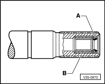
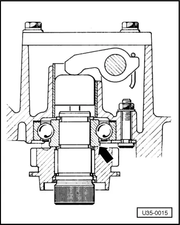
From 27 10 7

→ Fig.7     Position of seal and bush

A -

Pulling seal out: Fig. 8
Installing: =>Fig. 9

B -

Bush for clutch push rod
Removing: 10 mm drift
Installing: =>Fig. 10

Note:

The new seal and bush can be installed in gearboxes before Assy. date 27 10 7.

 
U35-0007

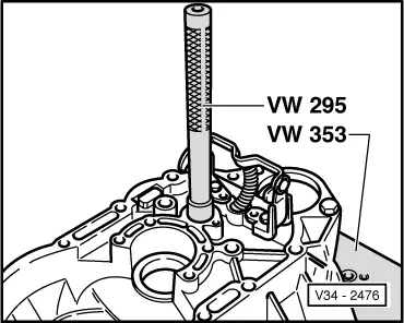
→ Fig.8     Pulling seal for clutch push rod out

 
V34-0790

→ Fig.9     Installing seal

  • ‒ Push seal -A- in with the fitting plug -B- supplied.
  • ‒ Take plug out. The seal is then in the correct position (0.8 - 1.3 mm deep).
  • ‒ Oil lips of seal.
 
U35-0008

→ Fig.10     Drive bush in fully

 
U35-0009

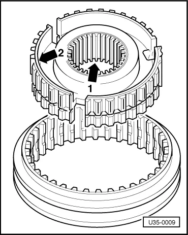
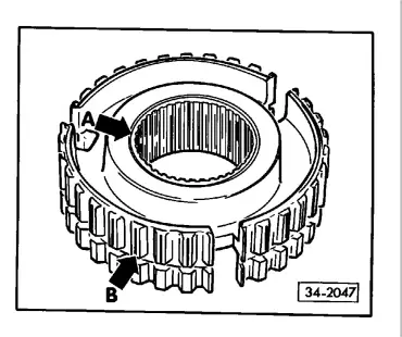
→ Fig.11     Assembling sleeve and hub for 3rd/4th gear

Position:

  •      1 -     The chamfer on the inner splines of the hub goes towards 3rd gear.
  •      2 -     Additional identification groove goes towards 4th gear.
 
U35-0010

→ Fig.12     Assembling sleeve/Hub

  • ‒ Place sleeve on hub. The parts are matched and the marks -arrow- must be aligned.
  • ‒ Install springs 120° offset. The angled end of the spring must engage in the hollow key.

Mod:

From 08 10 6

The etched line -arrow- marking the assembly position has been dropped. It is no longer necessary to fit in a certain position. When renewing, sleeve and hub must be renewed together.

Modification

From Assembly 04 08 5

 
34-2047

→ Fig.13     Hub for 3rd/4th gear with offset retaining groove

The groove in the splines was offset slightly and prevents jumping out of 4th gear more effectively.

Identification

Either a groove (arrow A) on hub (4th gear side) or axial grooves on the splines (arrow B)

Repair instructions

(Gearbox up to 03 08 5)

If 4th gear jump out or 3rd gear jams with vehicle stationary, install modified hub.

 
U35-0012

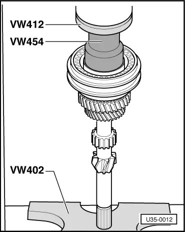
→ Fig.14     Pressing hub and sleeve on

Fitting direction =>Fig. 11

  • ‒ Turn synchronizer rings so that grooves align with keys.
 
U35-0013

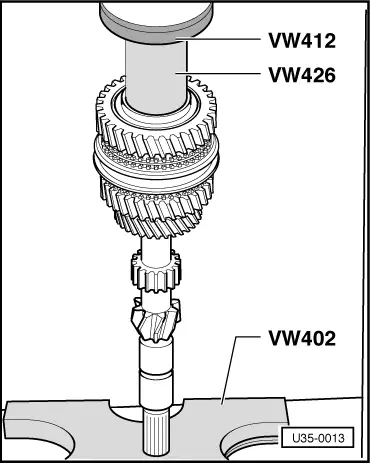
→ Fig.15     Pressing thrust washer on

Only up to 18 06 5

 
U35-0014

→ Fig.16     Pressing ball bearing and shim into the gearbox housing

Modification

From gearbox 19 06 5

 
U35-0015

→ Fig.17     Input shaft ball bearing with wider inner race

Shoulder on inner race -arrow- widened by thickness of 4th gear thrust washer. Thrust washer dropped.

Service installation

When installing new bearing in gearboxes up to number 18 06 5, remove 4th gear thrust washer.

 
U35-0016

→ Fig.18     Pulling drive shaft needle bearing out

  •      1 -     Extractor 18.5 - 23.5 mm, Kukko 21/3
 
V34-2476

→ Fig.19     Knocking in drive shaft needle bearing

Adjusting input shaft > < Additionally securing magnet in clutch housing with sealing compound