
Golf Mk1
|
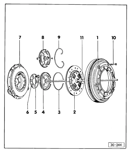
Clutch
Repairs to clutch (190/200 mm dia.)
|
 |
|
|
Note: When repairs are required to the clutch, the gearbox must be removed =>page 34-17 TDC sensor adapter in clutch housing=>page 34-76 When removing and installing the clutch in addition to the notes in the Workshop manual the following should be noted: Clean input shaft splines and with used clutch plates clean hub splines, remove corrosion and apply a very thin coat of G 000 100 grease to the input shaft, until the hub move freely on the shaft. Remove surplus grease without fail. Caution!
Assemble clutch so that the centering pins in flywheel engage the centering holes or slots in the pressure plate. Otherwise the TDC mark on flywheel will no longer be correct. |
|
|
|
|
|
|
 |
|
|
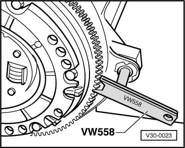
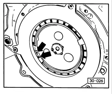
→ Fig.1 Removing and installing flywheel |
 |
|
|
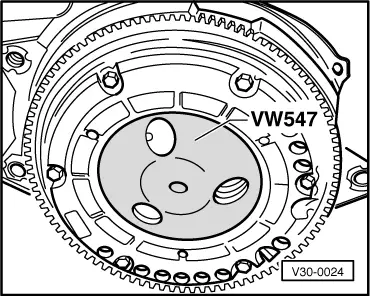
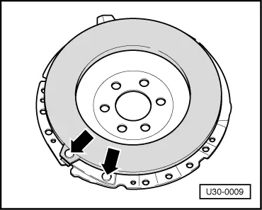
→ Fig.2 Installing clutch plate Tighten screws alternately and diagonally to 20 Nm |
 |
|
|
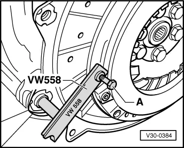
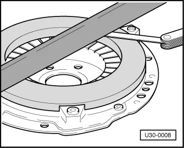
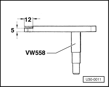
→ Fig.3 Removing and installing pressure plate Note: To fit the 200 mm clutch the retainer VW 558 must be reworked as shown in Fig. 9. |
 |
|
|
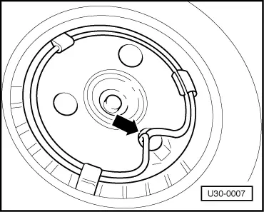
→ Fig.4 Installing retaining ring (190 mm clutch) Watch position of ring ends. |
 |
|
|
→ Fig.5 Installing retaining ring (200mm clutch) Watch position of ring ends. |
 |
|
|
→ Fig.6 Checking pressure plate for distortion, cracks and signs of burning Maximum inward taper 0,2 mm. |
 |
|
|
→ Fig.7 Check spring connections between pressure plate and cover for cracks, loose rivets and security Clutches with damaged or loose rivets should be renewed. |
 |
|
|
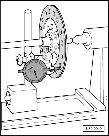
→ Fig.8 Checking clutch plate for lateral run-out May. 0.3 mm (measured 2.5 mm from outer edge) |
 |
|
|
→ Fig.9 Reworking retainer VW 558 The shaded area must be reworked to dimensions given. Note: The 200 mm dia. clutch can be service installed by replacing the pressure plate, flywheel, clutch plate, release plate and retaining ring. |