
Golf Mk1
|
Removing and installing parts of fuel system
Removing and installing fuel tank with attachments
|
 |
|
|
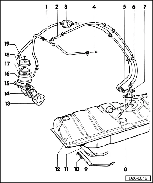
(40 litre tank) Part I
|
|
|
|
|
|
|
 |
|
|
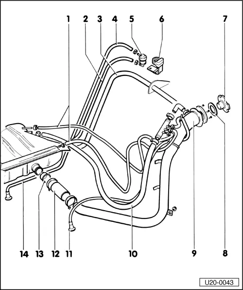
Part II
|
|
|
|
 |
|
|
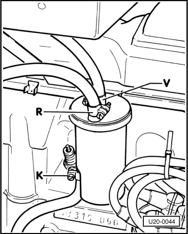
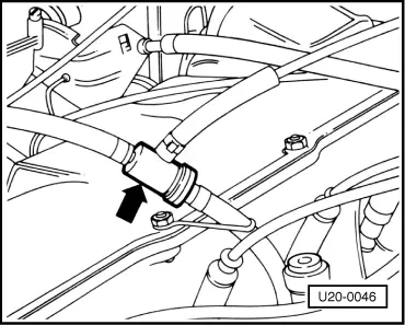
→ Fig.1 Fuel reservoir (plastic) Vehicles with 1B3 carburettor 06.80 ä are fitted with a reservoir (plastic). Connections: K - Fuel pump R - Return line V - Carburettor |
 |
|
|
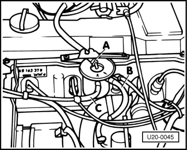
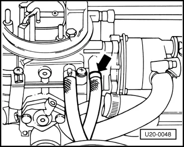
→ Fig.2 Fuel reservoir Vehicles with 2E2 carburettor are fitted with a reservoir (sheet steel). Connections: A - Carburettor (no marking) B - Fuel pump (arrow) C - Return line (R) |
 |
|
|
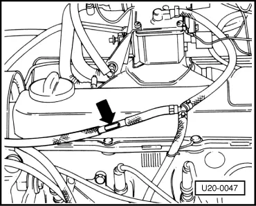
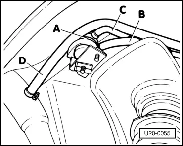
→ Fig.4 Fuel return line 08.75 äall vehicles feature a return line. ä07.78: Return line with restrictor -arrow- 08.78 ä : Restrictor in T piece |
 |
|
|
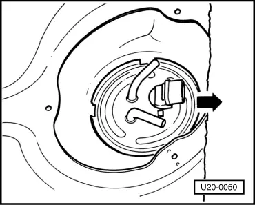
→ Fig.7 Installation position of fuel gauge sender Electrical connection must coincide with the broken line. Arrow points in direction of travel. |
 |
|
|
→ Fig.9 Testing check valve 03.77 ä there is a check valve in the fuel tank inlet connection. When repairing the fuel tank, ensure that valve moves easily and that it is installed correctly (hanging). Rules for cleanliness Pay attention to the following "5 rules" for cleanliness when working on the fuel system:
Removing and installing fuel tank (40 litre fuel tank) Removing Note rules for cleanliness => page 20-12 .
Note: If applicable, first interrogate the radio antitheft coding.
|
 |
|
Installing
=> Bleeding brake system; Repair Group 47; Note:
|