volkswagen Workshop Repair Guides

Volkswagen Workshop Service and Repair Manuals

Reworking valve seats > < Testing compression
4 Cyl injection engine (2 valve), Mechanics
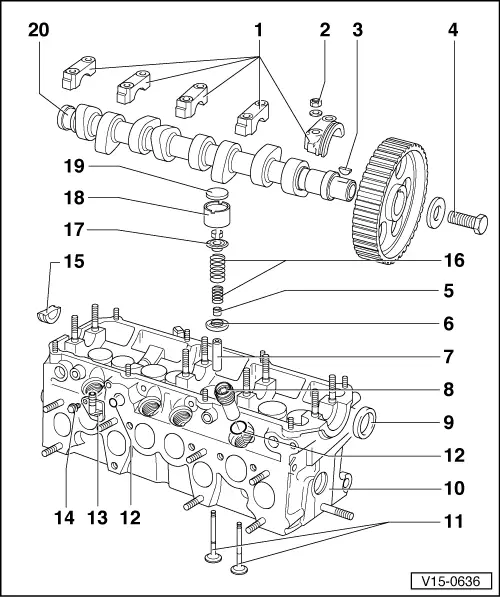
Servicing valve gear
 
V15-0636

Note:

Cylinder heads with cracks between valve seats or between a valve seat insert and spark plug thread can continue to be used without reducing service life when these are surface cracks with a maximum width of 5.0, or when only outer threads of the spark plug socket are damaged.

  • Bearing cap
    • ◆ Without bearing cap 4 with hydraulic tappets
    • ◆ Watch bore offset =>fig.2
    • ◆ For installation sequence see Camshaft installation
  • 20 Nm
  • Woodruff key
    • ◆ Ensure tight fit
 
V15-0636
  • 80 Nm
  • Valve stem oil seal
  • Lower spring seat
    • ◆ Remove and install with 3047
  • Valve guide
    • ◆ Checking wear
    • ◆ Renewing => page 15-29
  • Injector insert, 20 Nm
    • ◆ Coat thread with -D6-
    • ◆ ▸7/83 short version
      8/83...7/84 as shown
      8/84 ▸ two part version
    • ◆ Remove and install two-part version with 3135
  • Oil seal
    • ◆ Renew
 
V15-0636
  • Cylinder head
    • ◆ Exchange cylinder heads with camshaft bearing shells => fig.5
    • ◆ Reworking valve seats
    • ◆ Reworking dimension => fig.6
  • Valves
    • ◆ Grind in only, do not rework
    • ◆ Valve dimensions => fig.8
    • ◆ Checking and adjusting valve clearance
      Engine Code:
      DX and KT ▸7/85,
      JH ▸ 7/87, EG, JJ
  • Sealing ring
  • Air conection
    • ◆ 8/83 ▸
    • ◆ For air-shoulders injectors
 
V15-0636
  • 10 Nm
  • Sealing plug
    • ◆ Renew
  • Outer valve spring
    Inner valve spring
    • ◆ Removal and installation:
    • ‒ Cylinder head removed with 2037
    • ‒ Cylinder head installed
  • Upper valve spring seat
    • ◆ Identification => fig.7
  • Bucket tappets
    • ◆ Check axial clearance of camshaft before installation
    • ◆ Lubricate contact surfaces
    • ◆ Do not interchange
  •      -     Hydraulic tappets
    • ◆ Place with working surface downwards
    • ◆ Checking
 
V15-0636
  • Shim
    • ◆ Not with hydraulic tappets
    • ◆ Checking and adjusting valve clearance
  • Camshaft
    • ◆ Checking axial clearance fig.1
    • ◆ Removing and installing
    • ◆ Camshaft identification
      => fig.3 and4
    • ◆ Check radial clearance with Plastigage. Wear limit: 0.1 mm
    • ◆ Run-out: max. 0.01 mm
 
V15-0456

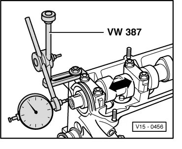
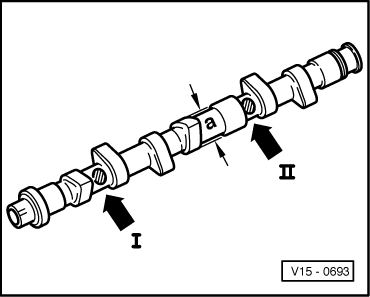
→ Fig.1     Camshaft, checking axial clearance

Wear limit: 0.15 mm

Check clearance with bucket tappets removed and bearings caps 1 and 5 installed.

 
V15-0098

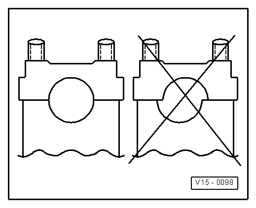
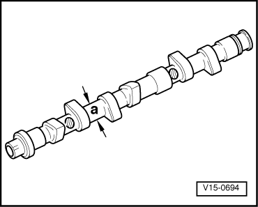
→ Fig.2     Position of camshaft bearing shells

Watch bore offset. Before installing camshaft, place bearing caps in position to determine correct installation position

 
U15-0003

→ Fig.3     Camshaft identification

For tappets with shim:

  • ◆ Pitch a circle of cams a = 38 mm diameter.

Identification - Engine Code EG

  • ◆ Up to Engine No. EG 186 191:
    Cast ring on first and third cams
    => Camshaft A -Arrow-.
  • ◆ from Engine No. EG 186 192:
    Stamped letter -G- or -N- between the cams of No.1 cylinder
    => Camshaft B -Arrow-.

Identification - Engine Codes, DX and KT ▸ 7/85, JJ

  • ◆ Stamped letter -G- or -N- between the cams of No. 1 cylinder
    => Camshaft B -Arrow-.

Identification - Engine Code JH ▸ 7/87

  • ◆ Cast on third cam
    => Camshaft A - right hand arrow
 
V15-0693

→ Fig.4     Camshaft identification

For hydraulic tappets

  • ◆ Pitch circle of cams a = 34 mm diameter
  • ◆ Identification mark between cams

Engine Codes

Cylinder 1 Arrow I

Cylinder 2 Arrow II

DX and KT 8/85 ▸
JH 8/87 ▸, 2H

G

026

 
V15-0694

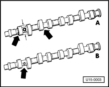
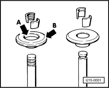
→ Fig.5     Replacement cylinder heads with camshaft bearing shells for the camshaft

In some cases replacement cylinder heads and replacement engines are suplied with bearing shells for the camshaft.

A - Cylinder head with normal-sized camshaft
     a = 26.00 mm diameter

B - Cylinder head with undersized camshaft
     b = 25.75 mm diameter and yellow paint spot on the VW-Audi emblem

 
U15-0001

Note:

The undersized camshaft is not supplied as a replacement part. When necessary, use normal camshaft with suitable bearing shells.

→ Fig.6     Cylinder head - reworking dimension

Minimum height: a = 132.6 mm

 
V15-0486

→ Fig.7     Valve versions

Engine Code EG:
     Single-groove valve (right)

Engine Codes DX, JH, JJ, KT, 2H:
     Three-groove valve (left)

Ensure that correct cotters and upper spring seats are installed.

Identification of upper spring seats for three-groove vale:

  • ◆ wide chamfer at the inside -Arrow A-
  • ◆ wide chamfer at the outside -Arrow B-
 
V15-0024

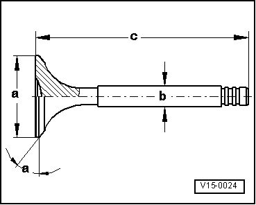
→ Fig.8     Valve dimensions

Bucket tappets

With shim

Hydraulic

Engine Codes

EG

DX, JH, JJ, KT

DX, JH, KT, 2H

Inlet valve

diameter a in mm

38.00

40.00

40.00

diameter b in mm

7.97

7.97

7.97

c in mm

105.7

98.70

91.00

α°

45

45

45

Exhaust valve

diameter a in mm

31.00

33.00

33.00

diameter b in mm

7.95

7.95

7.95

c in mm

105.5

98.50

90.80

α°

45

45

45

Important!
Valves are not to be machined. Only grinding - in by hand is permissible.

Reworking valve seats > < Testing compression