|
Wheels and tyres
Checking wheel alignment
A complete wheel alignment check can best be carried out with an optical measuring instrument such as VW 1237. If such an instrument is not available, the camber can be checked with a protractor VW 261 or 3021 and the toe with a mechanical track tester.
The following conditions are essential when checking the alignment:
-
● Test instrument must be properly adjusted.
-
● Vehicle must be unladen.
-
● Correct tyre pressures.
-
● Vehicle must be aligned and bounced properly (1).
-
● Correctly adjusted steering gear.
-
● Steering linkage free of play.
-
● Play in suspension not excessive.
Wheel alignment data
|
|
|---|
|
Front axle Golf/Jetta/Scirocco/Caddy
|
Suspension strut
|
|
|
Golf/Jetta/Scirocco/
|
Golf/Jetta/Scirocco/
|
|
|
Caddy all except 81 kW
|
Caddy with 81 kW
|
|
Total toe (not pressed)
|
|
+10'font=symbol charset=fontspecific code=042
|
|
|
-15'
|
|
|
|
equivalent
|
-15' -3 to -0,5 mm
|
|
Camber (in straight-ahead position)
|
+20' ± 30'
|
+20' ± 20'font=symbol charset=fontspecific code=042
|
|
Maximum permissible difference between sides
|
1°
|
30'
|
|
Toe angle difference at 20° lock lo left and right (not adjustable)
|
|
-1° 30' ±30'
|
|
Caster ange (not adjustable)
|
|
1° 50' ±30'
|
|
corresponds to camber difference of a wheel on a lock from 20° left to 20° right
|
|
|
|
Maximum permissible difference between sides
|
|
1° 15' ±20'
max. 1°
|
|
|
|---|
|
Rear axle Golf/Jetta/Scirocco
|
Torsion beam axle
|
|
Camber2) (not adjustable)
|
|
|
-1° 15' ±25'
|
|
up to Chassis No. Golf
|
175 3 241 690
|
|
|
|
Scirocco
|
536 2 031 722
|
-1° ±35'
|
|
|
from Chassis No. Golf
|
176 3 241 691
|
|
|
|
Scirocco
|
536 2 031 723
|
-1° 15' ±35'
|
|
|
Maximum permissible difference between sides
|
max. 40'
|
|
Total toe (not adjustable)
|
|
|
+20` ± 20`
|
|
up to Chassis No. Golf
|
176 3 241 690
|
|
|
|
Scirocco
|
536 2 031 722
|
+10' ±30'
|
|
|
from Chassis No. Golf
|
176 3 241 691
|
|
|
|
Jetta
|
16A 0 000 001
|
|
|
|
Scirocco
|
536 2 031 723
|
+20' ±20'
|
|
|
Maximum permissible deviation from alignment3)
|
max. 30'
|
1) Do not check alignment before 1000 - 2000 km to give springs time to settle.
2) If not correct, check vehicle lateral angle. The vehicle should be horizontally level to give accurate results.
3) Working out the alignment - see following.
font=symbol charset=fontspecific code=042 For really sporting driving, the toe can be set at - 10' to 0' and the camber at + 40'.
Note:
Keep as close as possible to the specified figures when setting the suspension.
|
|
|---|
|
Rear axle Caddy
|
Rigid axle
|
|
Camber1) (not adjustable)
|
0° ± 10'
|
|
Maximum permissible difference between sides
|
max. 30'
|
|
Total toe (not adjustable)
|
0° ± 1°
|
|
Maximum permissible difference between sides
|
max. 30'
|
1) If not correct, check vehicle lateral angle. The vehicle should be horizontally level to give accurate results.
Working out alignment
-
‒ If both toe angles have the same sign (+ / + or - / -), take small figure from large one and divide by 2.
|
|
|---|
|
Example:
|
|
Deviation from alignment
|
|
Toe of left rear wheel
|
+ 15'
|
15'- 5' = 10'
|
|
Toe of right rear wheel
|
+ 5'
|
10': 2 = 5'
|
|
|
|
= 5'
|
-
‒ If signs are different (+ / -), add values and divide total by 2,
|
|
|---|
|
Example:
|
|
Deviation from alignment
|
|
Toe of left rear wheel
|
+ 15'
|
15'+5' = 20'
|
|
Toe of right rear wheel
|
- 5'
|
20':2 = 10'
|
|
|
|
= 10'
|
The result in each case is the actual deviation of alignment from vehicle axis.
Adjusting camber
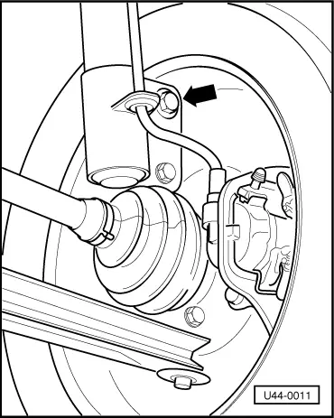
Adjust by rotating the eccentric bolt (arrow). (Adjustment range approx. 2°.)
- 1 - Slacken off the wheel bearing housing nuts on suspension strut.
- 2 - Rotate the eccentric camber adjusting bolt until the correct camber is attained.
- 3 - Tighten securing nuts, recheck camber. If necessary correct.
- 4 - Check toe, and if necessary correct.
Adjusting toe
- 1 - Adjust toe by rotating the right-hand tie rod. If necessary, remove securing ring, straighten boot and fit ring again.
The lugs on the ring must point upwards. The boot must not be twisted.
Note:
When two adjustable tie rods are fitted (only adjustable tie rods are available as Service Parts, see also removing and installing tie rods ) the right-hand tie rod only is to be adjusted.
| 
