
Golf Mk2
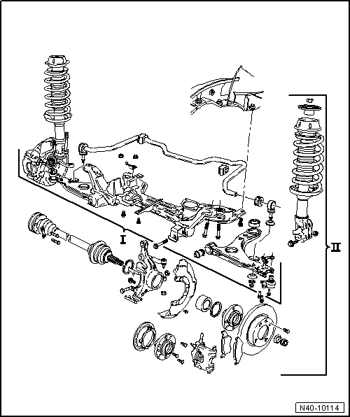
| Removing and installing subframe, anti-roll bar and wishbone |
| I - Removing and installing subframe, anti-roll bar and wishbone → Chapter |
| II - Removing and installing wheel bearing, suspension strut, drive shaft → Chapter |
 Note
Note| t | If a vehicle has to be moved after removing the drive shaft, first install an outer joint instead of a drive shaft, otherwise the wheel bearing will be damaged. |
| t | Wheel alignment specifications → Chapter |
| t | It is not permitted to weld or straighten suspension parts which bear loads or locate the front wheels |
| t | Renew self-locking nuts. |
| t | Always renew corroded nuts and bolts. |
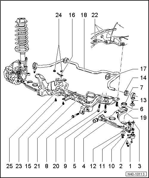
| 1 - | Hexagon bolt, 35 Nm |
| 2 - | Swivel joint |
| q | Check rubber bellows for damage, install a new swivel joint if necessary. |
| q | Modification: As of 08.87 pin Ø 19 mm, previously Ø 17 mm. |
| q | Mark installation position; if suspension link is renewed, set to centre of elongated hole. |
| q | Elongated holes are not used to set camber! Non-observance may lead to damage to drive shafts. |
| 3 - | Plate with nuts |
| 4 - | Suspension link |
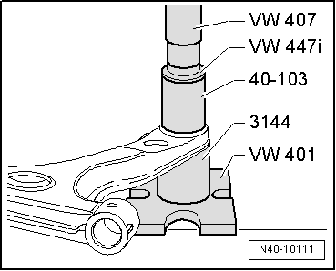
| 5 - | Front wishbone bush |
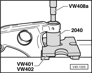
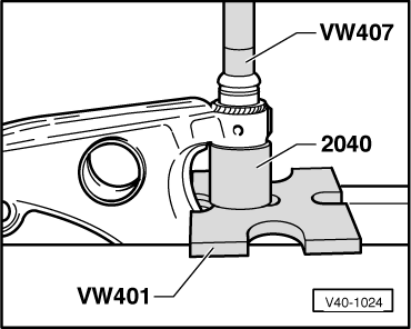
| q | Pressing out → Fig.. |
| q | Pressing in → Fig.. |
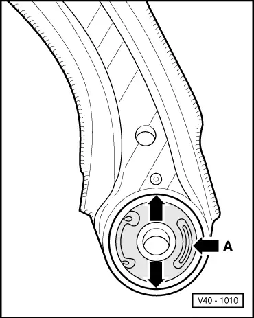
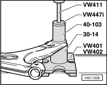
| 6 - | Rear wishbone bush |
| q | Pressing out → Fig.. |
| q | Pressing in → Fig.. |
| q | Installation position → Fig.. |
| 7 - | Metal sleeve, slotted |
| q | Pull out with pliers before removing suspension link. |
| q | Renew. |
| q | Not fitted in vehicles with G60 engine → Anchor. |
| 8 - | Hexagon bolt, 130 Nm |
| 9 - | Hexagon bolt M12×1.5 x 74, 130 Nm |
| q | Vehicle with G60 engine M12 x 1.5 x 78, 130 Nm. |
| 10 - | Self-locking hexagon nut, 25 Nm |
| 11 - | Washer |
| q | Collar faces away from bush. |
| 12 - | Connecting link mounting |
| q | Side with large depression to suspension link. |
| 13 - | Coupling rod |
| 14 - | Rubber bush |
| q | Before pressing in, coat with lubricant e.g. soft soap. |
| 15 - | Hexagon bolt, 25 Nm |
| 16 - | Clamp |
| 17 - | Rubber bush |
| 18 - | Anti-roll bar |
| q | Anti-roll bar allocation → Note. |
| 19 - | Hexagon bolt, 80 Nm |
| 20 - | Hexagon bolt M12×1.5 x 65, 130 Nm |
| 21 - | Subframe |
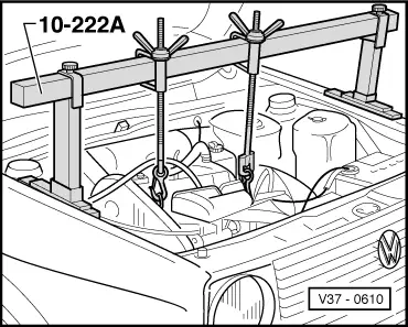
| q | Removing and installing when assemblies are installed: support assemblies → Fig.. |
| q | Remove subframe with suspension link (but without steering box) out downwards using engine and gearbox jack -V.A.G 1383-. After installing, check front wheel alignment and position of steering wheel. |
| q | Note subframe version → Chapter. |
| q | Assembly mounting → Chapter. |
| q | Aligning engine/gearbox assembly → Chapter. |
| 22 - | Cap nut |
| q | Reworking in longitudinal member → Chapter. |
| 23 - | Hexagon bolt |
| 24 - | Hexagon nut, 25 Nm |
| 25 - | Damper weight |
| q | Only fitted in vehicles with G60 engine. |
|
| Allocation model | No | With (Ø mm) |
| Golf 1.1 l, 1.3 l 1.6 l 55 kW 1.6 l diesel | x | |
| Golf 1.8 l, GTI, 16 V GTD, Jetta all | 18 | |
| Vehicle with G60 engine | 23 |
|
|
Note
|
|
|
|
|
|
|
|