volkswagen Workshop Repair Guides

Volkswagen Workshop Service and Repair Manuals

Servicing Climatronic - engine compartment > < Operation and function of the control and display unit
Heating, Air conditioning
Climatronic - Air conditioner with automatic regulation (R134a refrigerant)
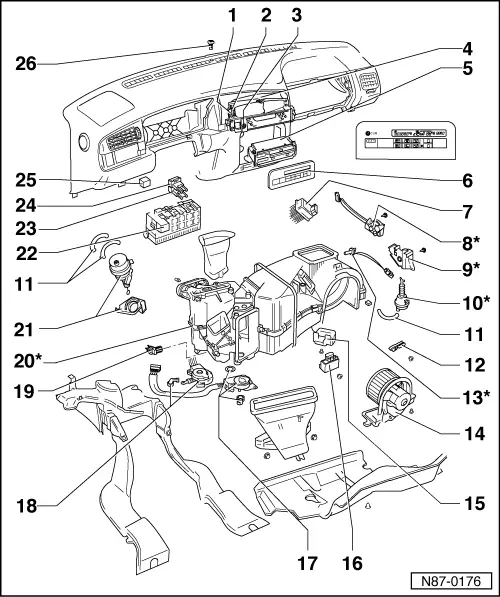
Servicing Climatronic - Passenger compartment
 
N87-0176

Notes:

  • ◆ Parts marked * can only be serviced in specially equipped Service workshops, as the refrigerant must be evacuated with Service station V.A.G 1885.
  • ◆ Removing and installing components without item numbers
  • Central vent positioning motor -V102-
    • ◆ Checking: self diagnosis using V.A.G 1551
    • ◆ Removing and installing: remove central vent -4-
 
N87-0176
  • Adjuster for central vent positioning motor -E160-
    • ◆ Checking: self diagnosis using V.A.G 1551
    • ◆ Removing and installing: remove central vent -4-
  • Dash panel temperature sensor -G56- with temperature sensor fan -V42-
    • ◆ Task: Temperature sensor controls temperature flap and fresh air blower in dependence on temperature
    • ◆ In event of -G56- failure: continued operation assuming value of +24°C
    • ◆ Checking: self diagnosis using V.A.G 1551
    • ◆ Removing and installing: remove central vent -4-
 
N87-0176
  • Central vent
    • ◆ Central vent, central vent positioning motor -1 -, adjuster for positioning motor -2 -, dash panel temperature sensor -3 - and temperature sensor fan -3 - are a single replacement part
    • ◆ Removing => Fig. 1
  • Climatronic control unit -J255-
    • ◆ Checking: self diagnosis using V.A.G 1551
    • ◆ Removing => Fig.3
  • Control and display unit -E87-
    • ◆ Operation and function
    • ◆ Checking: self diagnosis using V.A.G 1551
    • ◆ Removing => Fig.3
 
N87-0176
  • Blower control unit -J126-
    • ◆ Task: precisely controls fresh air blower speed depending on voltage
    • ◆ Checking: self diagnosis using V.A.G 1551
    • ◆ Removing => Fig.2
  • Air flow flap positioning motor -V71-*
    • ◆ Checking: Self diagnosis using V.A.G 1551
    • ◆ Removing: first remove dash panel and complete air conditioner
  • Guide flap*
 
N87-0176
  • Vacuum unit for fresh/recirculating air flap*
    • ◆ Removing: first remove dash panel and complete air conditioner
    • ◆ Vacuum hose connection diagram => Page 87-128
  • Vacuum pipe
    • ◆ Vacuum hose connection diagram => Page 87-128
  • Connector retainer
    • ◆ For connector -T5a-, to intake air control flap positioning motor -V71- and on vehicles up to 07.95 additionally retainer for connector -T2h- to fresh air intake duct temperature sensor -G89-
    • ◆ Removing and installing => Fig.4
 
N87-0176
  • Fresh air intake duct temperature sender -G89-*
    • ◆ Task: temperature sensor controls temperature flap and fresh air blower depending on temperature
    • ◆ In event of failure: ambient temperature sensor -G17- takes over task. If both sensors are defective, operation continues assuming value of +10°C. Air recirculation is not possible. Control and display unit -E87- reads: "--"
    • ◆ Checking: self diagnosis using V.A.G 1551
    • ◆ Removing: first remove air flow flap positioning motor -8 -.
 
N87-0176
  • Fresh air blower -V2-
    • ◆ Checking: self diagnosis using V.A.G 1551
    • ◆ Removing=> Fig.6
  • Evaporator temperature switch -E33-
    • ◆ Only installed in vehicles up to 07.93
    • ◆ Behind cover
    • ◆ Insertion depth of sensor tube: 330 mm
    • ◆ Task: prevents icing up
    • ◆ Switching temperatures: opens at or below -20 C
    • ◆ Checking: self diagnosis V.A.G 1551
    • ◆ Renewing => Fig.3
 
N87-0176
  • Valve strip -N53-
    • ◆ If no current is flowing in the valve strip, no vacuum is created
    • ◆ Removing and installing=> Fig.7
    • ◆ Vacuum hose connection diagram => Page 87-128
  • Central flap positioning motor -V70-
    • ◆ Checking: self diagnosis using V.A.G 1551
    • ◆ Removing and installing => Fig.8
  • Temperature flap positioning motor -V68-
    • ◆ Checking: self diagnosis using V.A.G 1551
    • ◆ Checking and adjusting end position of installed positioning motor
    • ◆ Removing: first remove central console
 
N87-0176
  • Front vent temperature sender -G152-
    • ◆ Only installed in vehicles from 08.95
    • ◆ Function: Controls the air distribution defrost/footwell and the fresh air blower speed dependent upon the vent temperature.
    • ◆ Emergency running in event of front vent temperature sender-G152- failure: Continued operation assuming value of +80°C
    • ◆ Checking: self diagnosis using V.A.G 1551
    • ◆ Removing and installing=> Fig.10
  • Distributor and evaporator housing*
    • ◆ With heat exchanger
    • ◆ with evaporator
 
N87-0176
  • Double vacuum unit - foot well/defrost flap
    • ◆ Vacuum hose connection diagram => Page 87-128
    • ◆ Removing and installing => Fig.9
  • Relay
    • ◆ Vehicles up to 07.95:
      Air conditioner system relay -J32- (control number 13 ) or Climatronic relay -J254- (control number 105)
    • ◆ Vehicles from 08.95:
      Air conditioner system shut-off relay -J365- (control number 147)
    • ◆ Vehicles from 08.95:
      Engine code 1Z; air conditioner magnetic clutch shut-off relay -J246- (control number 38)
  • Heating and air conditioning fuse -S23-
 
N87-0176
  • Climatronic control unit fuse -S101-
  • Air conditioner system shut-off relay -J365-
    • ◆ Only vehicles up to 07.95 and engine code ADY
    • ◆ Above relay plate
    • ◆ Control number 147
  • Sunlight penetration photo sensor -G107-
    • ◆ Tasks: controls temperature flap and fresh air blower depending on light intensity
    • ◆ In event of failure: control unit -J255- assumes fixed value
    • ◆ Checking: self diagnosis using V.A.G 1551
    • ◆ Removing and installing: unclip from dash panel using screwdriver
 
V87-1568

→ Fig.1     Removing central vent

  • ‒ Carefully lever out adjustable grilles -3- with tapered pliers
  • ‒ Remove radio
  • ‒ Lever out trim/seat heater switch -1- and trim -2-
  • ‒ Remove 4 screws (arrows)
  • ‒ Vento only: remove trim -4-
  • ‒ Remove central vent
 
V87-1567

→ Fig.2     Renewing blower control unit -J126-

  • ‒ Remove glove compartment.
  • ‒ Pull off connector -2- and remove screw -3-.
  • ‒ Seal area between series resistor -1- and air duct with AMV 176 000 05 before fitting.
 
V87-1569

→ Fig.3     Removing Climatronic control unit -J255- and control and display unit -E87-

  • ‒ Lever out control and display unit from below with screwdriver (arrows)

Note:

Control and display unit cannot be levered out from above as this could damage the display.

  • ‒ Remove ashtray
  • ‒ Remove 6 screws and console with switches
  • ‒ Remove control unit
 
V87-1566

→ Fig.4     Removing and installing connector retainer

  •      1 -     Screw
  •      2 -     Retainer
  •      3 -     Connector for air flow flap -V71-
  •      4 -     Connector for fresh air intake duct temperature sensor -G89- (only vehicles up to 07.95)
 
V87-1353

→ Fig.5     Replacing evaporator temperature switch -E33-

  •      1 -     Temperature switch with housing
  •      2 -     Rubber bush
  •      3 -     Sensor pipe with insertion depth marking
  •      4 -     Pan-headed capping screw
  •      5 -     Connector

Note:

In cases of repair the temperature switch need not be replaced, instead bridge contacts -5-.

 
V87-1352

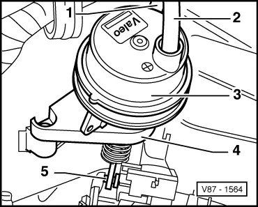
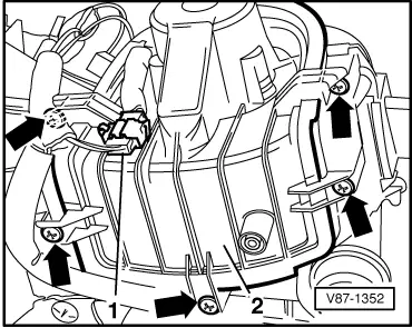
→ Fig.6     Removing and installing fresh air blower -V2-

  • ‒ Remove passenger side shelf.
  • ‒ Pull off connector -1-.
  • ‒ Unscrew Qty. 5 screws -arrows- and remove fresh air blower -2- downwards.
 
V87-1565

→ Fig.7     Removing and installing valve strip -N53-

  •      1 -     Valve strip
  •      2 -     Connector
  •      3 -     Vacuum hose, red
  •      4 -     Vacuum hose, green
  •      5 -     Vacuum hose, black
  •      6 -     Vacuum hose, yellow
  • ‒ Removing:
    • ‒ Remove glove compartment
    • ‒ Pull off vacuum hoses and connector
    • ‒ Unscrew valve strip -arrow-
  • ‒ Installing:
    • ‒ Use valve strip 357 907 533 as replacement part
    • ‒ Connect up vacuum hose according to colour coding on connection pipes (white connection on replacement part must be sealed with a cap).
 
V87-1562

→ Fig.8     Removing and installing central flap positioning motor -V70-

  •      1 -     Central flap positioning motor
  •      2 -     Intermediate gear
  •      3 -     Central flap bearing
  • ‒ Removing:
    • ‒ First remove central console
  • ‒ Installing:
    • ‒ For correct setting of central flap, markings -arrows- must be aligned
 
V87-1564

→ Fig.9     Removing and installing double vacuum unit

  •      1 -     Vacuum hose, green
  •      2 -     Vacuum hose, yellow
  •      3 -     Double vacuum unit
  •      4 -     Retainer
  •      5 -     Lever for footwell/defrost flap
  • ‒ Removing:
    • ‒ First remove central console
 
N87-0177

→ Fig.10     Removing and installing front vent temperature sender -G152-

  • ‒ Remove front left footwell trim
  • ‒ Pull connector -1- off front vent temperature sender -G152- -2-
  • ‒ Turn front vent temperature sender -G152- -2- by 90° and remove

Servicing Climatronic - engine compartment > < Operation and function of the control and display unit