volkswagen Workshop Repair Guides

Volkswagen Workshop Service and Repair Manuals

Vacuum hose connection diagram > < Servicing air conditioning and heating - engine compartment
Heating, Air conditioning
Refrigerant R12 - Air conditioner with manual controls
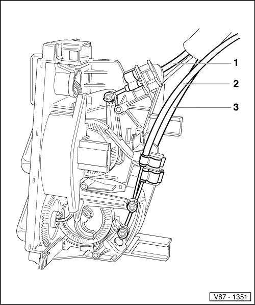
Installing and adjusting cables
 
V87-1351

Notes:

  • ◆ First connect cables to removed controls then adjust and secure cables to levers on air conditioner.
  • ◆ Sleeve ends of cables which are marked with a coloured line are attached to the controls.
  • ◆ Position cable sleeves at stops on the controls.
  • ◆ Adjust cables at flap levers with controls installed.
  • ◆ All flaps must audibly contact stop when controls are turned.
 
V87-1351
  • Cable for temperature control flap
    • ◆ From temperature rotary control knob to temperature control flap
    • ◆ Blue sleeve, 585 mm long
    • ◆ Adjusting cable at temperature control flap => Fig.1
  • Cable for footwell/defrost flap
    • ◆ From air distribution rotary control knob to footwell/defrost flap
    • ◆ Black sleeve, 488 mm long
    • ◆ Adjusting cable at footwell/defrost flap => Fig.2
  • Cable for central flap
    • ◆ From air distribution rotary control knob to central flap
    • ◆ Black sleeve, 639 mm long
    • ◆ Adjusting cable at central flap => Fig.3
 
V80-0481

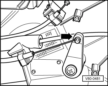
→ Fig.1     Adjusting cable at temperature flap

  • ‒ Install warm and fresh air blower controls.
  • ‒ Turn temperature rotary control knob to stop at "cold" position.
  • ‒ Press temperature flap lever onto stop -arrow- and secure blue cable sleeve.
 
V80-0482

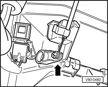
→ Fig.2     Adjusting cable at footwell/defrost flap

  • ‒ Install warm and fresh air blower controls.
  • ‒ Turn air distribution rotary control knob to stop at "defrost" position.
  • ‒ Press footwell/defrost flap lever onto stop -arrow- and secure black cable sleeve.
 
V87-1519

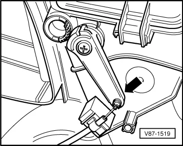
→ Fig.3     Adjusting cable at central flap

  • ‒ Install warm and fresh air blower controls.
  • ‒ Turn air distribution rotary control knob onto stop at "defrost" position.
  • ‒ Press central flap lever onto stop -arrow- and secure black sleeve.

Vacuum hose connection diagram > < Servicing air conditioning and heating - engine compartment