volkswagen Workshop Repair Guides

Volkswagen Workshop Service and Repair Manuals

Installing and adjusting cables > < Servicing air conditioning and heating - Passenger compartment
Heating, Air conditioning
Refrigerant R134a - Air conditioner with manual controls
Servicing air conditioning and heating - Engine compartment
 
N87-0037

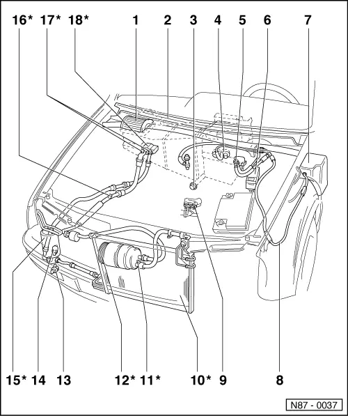
Note:

Parts marked with an * can only be serviced by specially equipped service workshops, as refrigerant must be evacuated with Service station V.A.G 1885.

  • Dust and pollen filter
    • ◆ Removing , Item -4 -
  • Plenum chamber cover
    • ◆ Removing and installing => Page 80-1 , Item -3 -
  • Water drain valve
    • ◆ Behind bulkhead insulation
    • ◆ Removing and installing => Fig.2
 
N87-0037
  • Heat exchanger and vacuum hose guide
  • Two way valve for fresh/recirculating air flap -N63-
    • ◆ Open when electrically connected
    • ◆ Vacuum hose connection diagram => Page 87-70
  • Radiator fan control unit -J293-
    • ◆ Note Part No.
  • Vacuum reservoir
    • ◆ Insertion depth for vacuum hose: 30 mm
    • ◆ Removing and installing => Fig.5
  • Vacuum hose
    • ◆ Vacuum hose connection diagram => Page 87-70
 
N87-0037
  • Thermo switch for air conditioner cut-off -F163- and thermo switch for coolant fan, 3rd speed -F165-
    • ◆ Thermo switch for air conditioner shut-off -F163- only on vehicles with engine codes AAA, AAZ, ABF and ADZ
    • ◆ Thermo switch for coolant fan, 3rd speed -F165- only on vehicles with 3-speed fan motor
    • ◆ -F165- switch coolant fan: into 3rd speed as temperature increases (on at 112°C, off at 108°C).
    • ◆ -F163- switches off magnetic coupling -N25- at excessively high coolant temperature (off at 119°C, on at 112°C).
    • ◆ Removing and installing on vehicles with engine code AAA => Fig.3
    • ◆ Removing and installing on vehicles with engine code ABF => Fig. 4
 
N87-0037
  • Condenser*
  • Pressure relief valve*
  • Magnetic coupling -N25-*
  • Ambient temperature switch -F38-
    • ◆ Switches off magnetic coupling -N25- at low ambient temperature (off at 2°C, on at 7°C).
    • ◆ Vehicles up to 07.95:
      Removing and installing => Fig.6
    • ◆ Vehicles from 08.95:
      Located in plenum chamber, right; Removing and installing => Fig. 7
  • Air conditioner pressure switch -F129-
    • ◆ Checking air conditioner pressure switch -F129- => Page 87-145
    • ◆ Removing and installing:
    • ‒ Tightening torque 8 Nm
    • ‒ Renew O ring seal (note Part No.).
 
N87-0037
  • Fluid reservoir with drier*
  • Sight glass*
  • Evacuating and charging valve*
  • Expansion valve*
    • ◆ Checking insulation piece for expansion valve => Fig.1
 
V87-1357

→ Fig.1     Checking expansion valve insulation piece

  •      1 -     Insulator
  •      2 -     Expansion valve
  • ◆ The insulator prevents drop in air conditioner efficiency caused by increasing temperatures in the engine compartment.
 
V87-1442

→ Fig.2     Removing and installing water drain valve

  •      1 -     Water drain valve
  •      2 -     Bulkhead
  •      3 -     Water drain pipe, on evaporator housing
  •      4 -     Mounting plate
  • ◆ Install water drain valve with opening of lip seal facing downwards.
  • ◆ Water drain valve must not be clogged with underbody sealant.
 
V87-1444

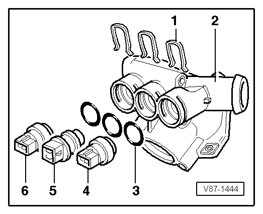
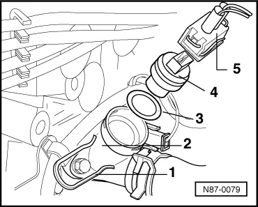
→ Fig.3     Removing and installing thermo switch for air conditioner shut-off -F163- and thermo switch for coolant fan, 3rd speed -F165- on vehicles with engine code AAA

Notes:

  • ◆ Cooling system is pressurized when engine is warm. If necessary, release pressure before carrying out repairs.
  • ◆ Refill with coolant after installing thermo-switch.
  •      1 -     Clip
  •      2 -     Thermostat housing
  •      3 -     O ring
  •      4 -     Thermo switch -F163-/-F165-, brown
  •      5 -     Temperature sender switch -G2-/-F87-, yellow
  •      6 -     Coolant temperature sender -G62-, blue
 
N87-0079

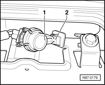
→ Fig.4     Removing and installing thermo switch for air conditioner shut-off -F163- on vehicles with engine code ABF

Notes:

  • ◆ Cooling system is pressurized when engine is warm. If necessary, release pressure before carrying out repairs.
  • ◆ Refill with coolant after installing thermo-switch.
  •      1 -     Clip
  •      2 -     Connection
  •      3 -     O ring
  •      4 -     Air conditioner cut-off thermo switch -F163-
  •      5 -     Connector
 
V87-1359

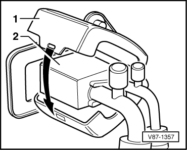
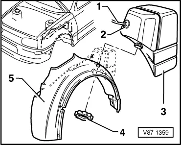
→ Fig.5     Removing and installing vacuum reservoir

  •      1 -     Plastic pipe
    • Installation depth: 30mm
  •      2 -     Rubber seal
  •      3 -     Vacuum reservoir
  •      4 -     Nut
  •      5 -     Wheel housing liner
  • ◆ Removing and installing wheel housing liner

=> General body repairs; Repair Group 66; Removing and installing wheel housing liner

 
V87-1445

→ Fig.6     Removing and installing ambient temperature switch -F38-

(Vehicles up to 07.95)

  •      1 -     Hexagon bolt, M8
    • Torque setting 15 Nm
  •      2 -     Ambient temperature switch bracket
  •      3 -     Horn bracket
  •      4 -     Plastic clip
  •      5 -     Ambient temperature switch
  •      6 -     Horn
 
N87-0179

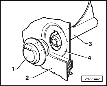
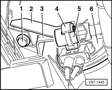
→ Fig.7     Removing and installing ambient temperature switch -F38-

(Vehicles from 08.95)

Note:

Removing and installing right-hand plenum chamber cover => Page 80-1 , item -3 -.

  •      1 -     Ambient temperature switch
  •      2 -     Plastic clip

Installing and adjusting cables > < Servicing air conditioning and heating - Passenger compartment