
Golf Mk3
|
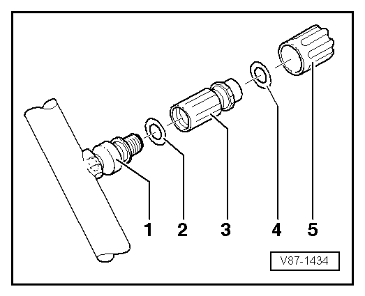
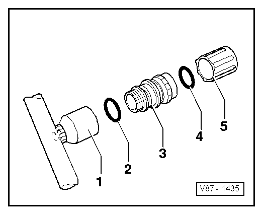
Repair work on the refrigerant circuit which can only be carried out by properly trained mechanics (Specialist workshops for air conditioning systems)
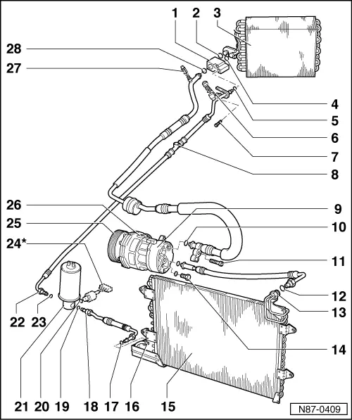
Servicing components in the refrigerant circuit
|
 |
|
|
Notes:
|
|
|
Function
|
|
|
|
|
|
|
|
|
|
|
|
|
|
|
|
|
|
 |
|
|
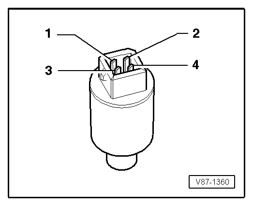
→ Checking switch part:
Switch part between chamber 3 and chamber 4 of connector housing switches radiator fan -V7- via radiator fan control unit -J293- to 2nd speed when refrigerant pressure rises.
Evaluating the checks on the pressure switch for the air conditioner -F129-
|
|
|
|
→ To assess the air conditioning system output perform and evaluate the following checks:
|