|
Fig.4
→
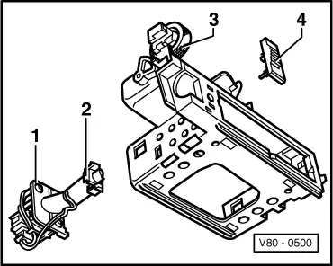
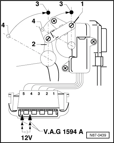
Checking end position of control motor -V68- when installed
-
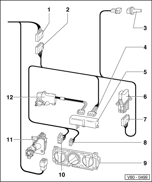
‒ Pull 5-pin connector off control unit -J214-
-
‒ Connect cables from adapter set V.A.G 1594 A to chambers 4 and 5.
-
‒ Connect to 12 V supply. Direction of rotation can be changed by reversing polarity of voltage supply.
-
‒ Move temperature flap -2- with control motor -1- from heater end position -4- to fresh air end position -3-.
-
‒ Check whether the temperature flap lever -2- reaches the stop when at the end position. If necessary, adjust length of connecting rod -1- with temperature flap -2- on stop.
Note:
If the connecting rod has been loosened, the rotary control is to be turned to the blue mark "cold" and the temperature flap lever must be pretensioned by pressing lightly towards cold and secured (4 clips).
|