volkswagen Workshop Repair Guides

Volkswagen Workshop Service and Repair Manuals

Removing and installing gearbox and bevel box (Vehicles with 6 cylinder fuel injection engine) > < Removing and installing gearbox
5-Speed manual gearbox 02C four wheel drive
Removing and installing gearbox
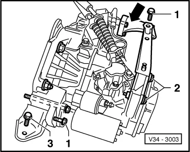
Removing and installing gearbox and bevel box (Vehicles with 4 cylinder engine)

Special tools, testers and auxiliary items

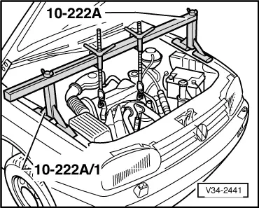
  • ◆ Engine support bracket 10-222A with supports10-222A/1
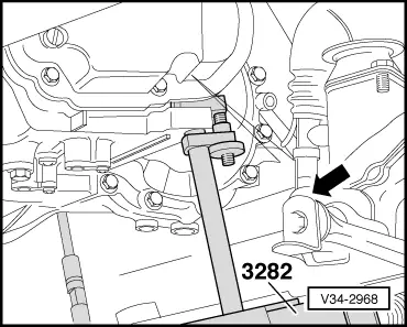
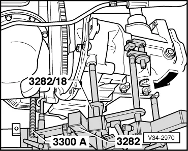
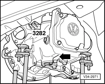
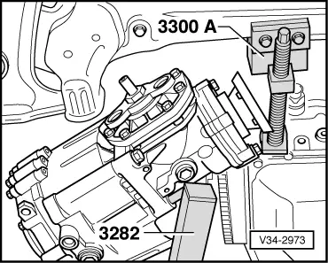
  • ◆ Gearbox support 3282
  • ◆ Alignment plate 3282/18
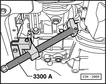
  • ◆ Engine press tool 3300 A
  • ◆ Engine/gearbox jack V.A.G 1383 A
  • ◆ Torque wrench V.A.G 1332

Removing

  • ‒ Loosen hexagon nut on left drive shaft.

Note:

Only loosen and tighten drive shaft hexagon nuts with vehicle standing on its wheels. (Danger of accident).

  • ‒ For vehicles with coded radio obtain radio code.
 
N34-0666
  • ‒ With the ignition switched off disconnect the battery earth strap.
  • ‒ Remove battery and console, lay P.A.S. reservoir to one side and secure with wire.
  • ‒ → Pull off speedometer sender connector (arrow 1) and reverse light connector (arrow 2).
  • ‒ Remove protective cap -arrow 3-.
  • ‒ Disconnect wiring harness/engine connector (arrow 4).
 
V34-2966
  • ‒ → Remove balance weight -A- and gear selector cable -B- from gear selector lever.
  • ‒ Pull gate selector cable -C- off actuating arm/relay lever, to do this lift lug in direction of arrow.
 
V34-2671
  • ‒ → Remove cable support bracket from gearbox (arrows).
 
V34-2672
  • ‒ → Remove slave cylinder and secure to side with wire, do not open pipes.

Note:

Do not depress clutch pedal.

  • ‒ Remove starter.

=> Repair group 27; Electrical system

  • ‒ Remove earth strap at engine/gearbox upper securing bolt.
  • ‒ Remove upper engine/gearbox securing bolts.
  • ‒ Remove air hose from between air cleaner and air intake elbow.
 
V34-2429
  • ‒ → Remove right-hand engine console/sub-frame securing bolt (arrow), first remove cable connector retaining plate -A- if fitted.
 
V34-2441
  • ‒ → Fit support bar 10-222 A together with legs 10-222 A/1 and support engine/gearbox.
 
V34-2440
  • ‒ → Disconnect engine carrier at front console.
  • ‒ Remove coolant system expansion reservoir and lay to one side.

Note:

Do not open cooling system.

 
V34-2680
  • ‒ → Remove hexagon bolt -A- from left hand hand assembly mounting -B-.
  • ‒ Remove power assisted steering pipe bracket from gearbox.
  • ‒ Remove power assisted steering pipes from front engine mounting.
 
V34-2965
  • ‒ Remove air ducting.
  • ‒ → Remove front engine mounting -arrows-.
 
V34-2098
  • ‒ → Remove bevel box/engine support.
 
V34-2974
  • ‒ → Remove balance weight -A- from sub-frame.
  • ‒ Remove heat shield from vehicle floor.
  • ‒ Separate exhaust system in front of catalyst.

=> Repair group 26; Removing and installing parts of exhaust system.

 
V34-2668
  • ‒ → Remove gearbox support -A- from gearbox.
 
V34-2101
  • ‒ Disconnect left and right drive shaft at gearbox drive flange.
  • ‒ Mark position of propshaft with flexible coupling to bevel box flange.
  • ‒ → Disconnect propshaft flexible coupling from bevel box flange (arrows).
  • ‒ Push propshaft back onto stop.
 
V39-1817

Note:

→ When removing and installing the gearbox do not damage the sealing ring in the propshaft flange.

  • ‒ Remove large clutch cover plate.
 
V34-3005
  • ‒ → Remove small cover plate -A- behind right-hand drive flange (arrows).
 
V34-2099
  • ‒ → Remove bevel box carrier from engine and bevel box (arrows).
 
V34-2967
  • ‒ → Remove left air duct -A- by driving clips out with a drift through holes in wishbone (arrows).
  • ‒ Assemble gearbox support 3282.

Adjustment plate 3282/18 is required to remove gearbox 02C with bevel box, using gearbox support 3282.

The symbols on the adjustment plate show the supports required.

 
V34-2964
  • ‒ → To enable the hook of gearbox support 3282 to engage remove bolt (arrow) in bevel box.
  • ‒ Place jack V.A.G 1383 A with gearbox support 3282 under the gearbox and support the gearbox.
  • ‒ Remove lower engine/gearbox securing bolts.
  • ‒ Turn wheels fully onto left lock.
 
V34-2968
  • ‒ → Lift engine/gearbox using support unit 10-222A spindles until there is sufficient clearance at sub-frame (arrow) to allow gearbox to be pressed off engine.
  • ‒ Press gearbox off engine.
 
V34-2969
  • ‒ → Set up press tool 3300 A .
  • ‒ Press engine and gearbox forwards.
 
V40-1311
  • ‒ → Separate left ball joint/wishbone connection. (Mark installation position first).
  • ‒ Remove left drive shaft.
 
V34-2970
  • ‒ Press gearbox further off engine.
  • ‒ → Swing gearbox to rear to gain clearance between flywheel and bevel box housing.
  • ‒ Thereby press gearbox further off engine.
 
V34-2971
  • ‒ → Swing gearbox forwards (arrow), lower slightly and set at an angle using gearbox support 3282 so as to maintain clearance between body and top of gearbox.
 
V34-2972
  • ‒ → Remove gearbox console.
 
V34-2973
  • ‒ → Lower gearbox.

Notes:

  • ◆ Do not damage P.A.S. pipe when lowering gearbox.
  • ◆ Ensure that the gearbox does not contact sub-frame and press tool 3300 A.
  • ◆ If the vehicle is to be moved with the drive shaft removed, then whilst the vehicle is still raised install an outer joint and tighten to 50 Nm. Otherwise the wheel bearing will be damaged.
  • ◆ If the vehicle is to be moved with the propshaft detached then secure the propshaft to prevent damage.
 
V34-2877

Installing

Installation is carried out in the reverse sequence, when doing this note the following:

  • ‒ → Before installing gearbox press clutch release lever towards gearbox housing and secure with assembly pin, assembly bolt or M8 x 35
    bolt. Remove after gearbox has been installed.
  • ‒ When installing ensure dowel sleeves are seated correctly.
  • ‒ Clean and lightly grease clutch release bearing, release bearing guide sleeve and input shaft splines with G 000 100 grease.
 
V34-2972
  • ‒ Before swinging gearbox in to installation position:
    • ‒ Insert left hand drive shaft.
    • ‒ → Tighten left gearbox console to correct tightening torque => Tightening torques, Page 34-36 .
  • ‒ When swinging in gearbox do not damage seal in propshaft flange.
  • ‒ Install bevel box/engine carrier stress-free .
 
V10-1229
  • ‒ → When installing the engine mounting ensure that the rib on the rear right console also the recess on the front console locates on the lugs of the bonded rubber mounting -arrows-.
  • ‒ Lock assembly, when installing to align engine/gearbox mountings stress-free.
  • ‒ Always renew drive shaft hexagon nuts.
  • ‒ Check oil level => Page 34-71 .
  • ‒ Specifications => Page 00-3 .
  • ‒ Adjusting gear selector mechanism => Page 34-17 .
 
V34-2743

Tightening torques

→ Gearbox to engine

Pos.

Bolt

Qty.

Nm

1

M 12 x 55

2

80

2

M 12 x 64

1

80

31)

M 10 x 140

2

60

4 2)

M 7 x 12

2

10

5 2)

M 6 x 8

1

10

     1)     Also starter to gearbox

     2)     Flywheel cover plate

Pos. A + B - Dowel sleeves

Tightening torques for bevel box/engine gearbox carrier => Page 34-62 .

 
V34-3003

→ Assembly mountings

Pos.

Bolt

Qty.

Nm

1

M 10 x 45

2

50

2

M 10 x 62

2

45

31)

M 10 x 30

1

50

     1)     as combi bolt M 10 x 32

Left console to gearbox (arrow)

25 Nm

Right engine console to sub-frame

25 Nm

Front engine carrier to side member

45 Nm

Selector cable support bracket to gearbox

25 Nm

Bevel box support to engine

40 Nm


Bevel box support to bevel box


40 Nm

Propshaft to bevel box

=> Page 39-86

Balance weight to sub-frame

30 Nm

Drive shaft to wheel bearing housing

265 Nm

Drive shaft to flange shaft/drive flange.

45 Nm

Removing and installing gearbox and bevel box (Vehicles with 6 cylinder fuel injection engine) > < Removing and installing gearbox