Golf Mk3
|
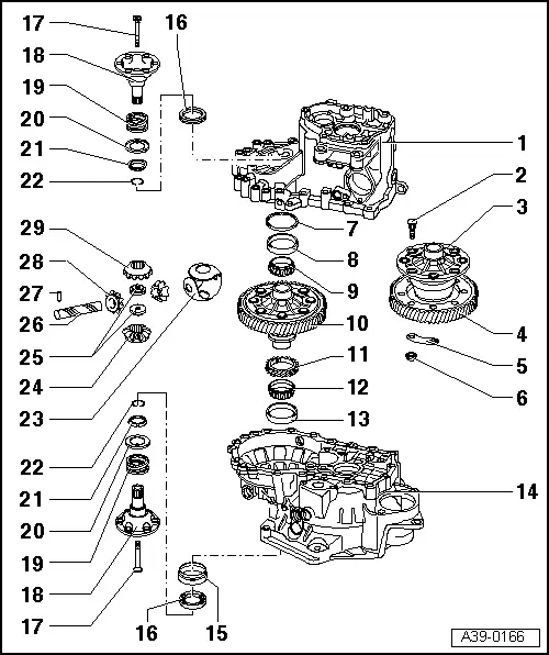
Dismantling and assembling differential
Dismantling and assembling differential
|
 |
|
|
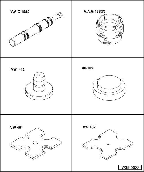
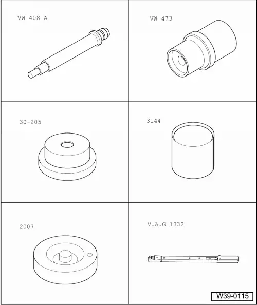
Special tools and workshop equipment required
|
 |
|
|
Special tools and workshop equipment required
Special tools and workshop equipment required |
 |
|
|
 |
|
|
Notes:
|
|
|
|
|
|
|
|
|
|
|
|
|
|
|
 |
|
|
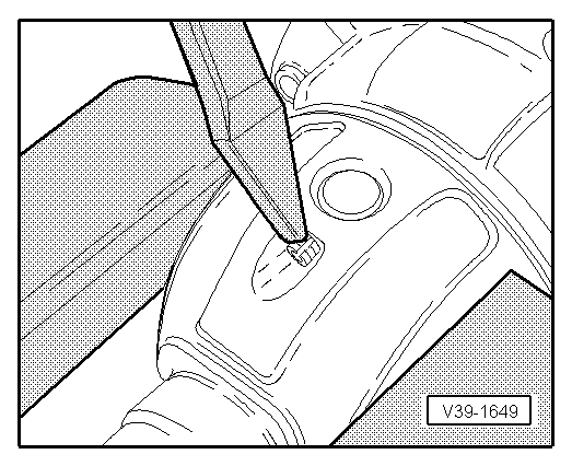
→ Fig.1 Knocking taper roller bearing outer race out of clutch housing
|
 |
|
|
→ Fig.2 Pressing taper roller bearing outer race into clutch housing No shim is installed in the clutch housing end. |
 |
|
|
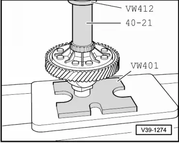
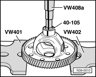
→ Fig.4 Pressing on taper roller bearing inner race Note: The taper roller bearing inner races for gearbox housing and clutch housing are pressed on with the same press tools. |
 |
|
|
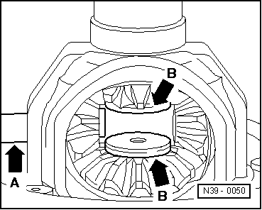
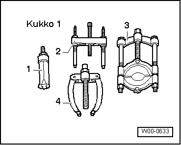
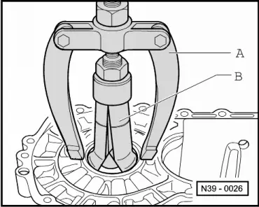
→ Fig.5 Pulling taper roller bearing outer race out of gearbox housing A - Counter support, e.g. Kukko 22/2 B - Internal puller 46...58 mm, e.g. Kukko 21/7 |
 |
|
|
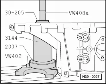
→ Fig.6 Pressing taper roller bearing outer race into gearbox housing
|
 |
|
|
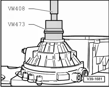
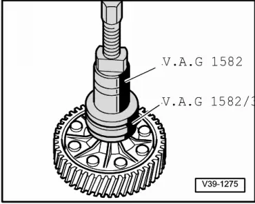
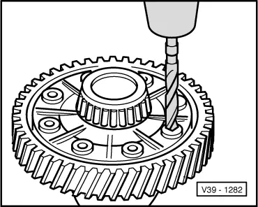
→ Fig.8 Pressing off final drive gear
|
 |
|
|
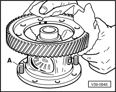
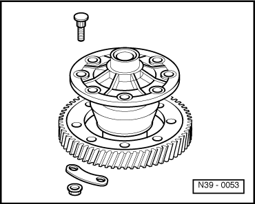
→ Fig.9 Installation position of final drive gear wheel The circular groove -A- faces towards bolt-on side of differential. |
 |
|
|
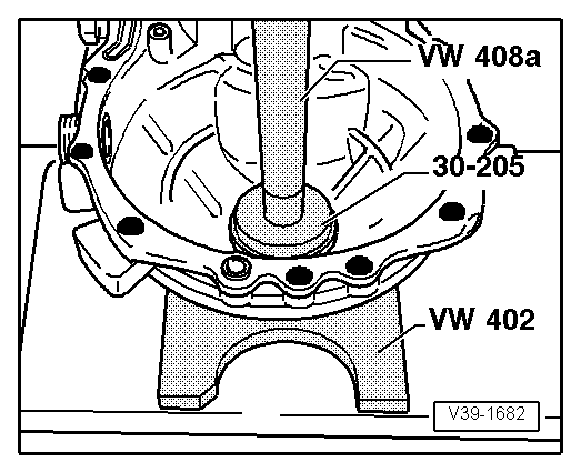
→ Fig.10 Heating final drive gear wheel to approx. 100 °C and installing
|
 |
|
|
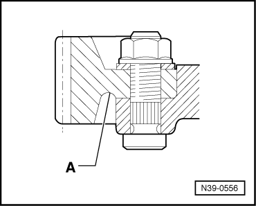
→ Fig.11 Bolting final drive gear and differential housing together Use special bolts with plates and nuts according to parts catalogue. |