volkswagen Workshop Repair Guides

Volkswagen Workshop Service and Repair Manuals

Removing and installing starter bush > < Fault finding table for "4-speed automatic gearbox"
Automatic gearbox 01M - from 01.95
Removing and installing gearbox

Special tools, testers and auxiliary items

  • ◆ Engine support bracket 10-222A with supports10-222A/1
  • ◆ Adapter 10-222A/3 (6-cylinder engine)
  • ◆ Hose clamps 3094
  • ◆ Gearbox support 3282
  • ◆ Alignment plate 3282/2
  • ◆ 3300 A
  • ◆ Engine/gearbox jack V.A.G 1383 A
  • ◆ V.A.G 1331 Torque wrench (5...50 Nm)
  • ◆ V.A.G 1332 Torque wrench (40...200 Nm)

Removing

  • ‒ Obtain radio code on vehicles with coded radio.
  • ‒ Disconnect battery earth strap.
    • ‒ Remove battery on vehicles with 6-cylinder engines.
  • ‒ Disconnect speedometer connector at gearbox.
 
V37-1048
  • ‒ Disconnect speedometer sender -G68- connector.
  • ‒ → Remove electrical connections (arrows) at gearbox.
  • ‒ Remove wiring harness from retainer and place to the side.
 
N37-0063
  • ‒ → Pull connector off multi-function switch.
    • ‒ Remove multi-function switch on vehicles with 6-cylinder engine.
  • ‒ Move selector lever to "P" and unscrew selector lever cable from lever/selector shaft.
  • ‒ Remove selector lever cable anchorage circlip and remove selector lever cable.

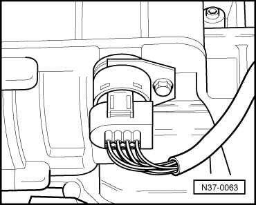
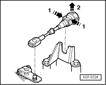
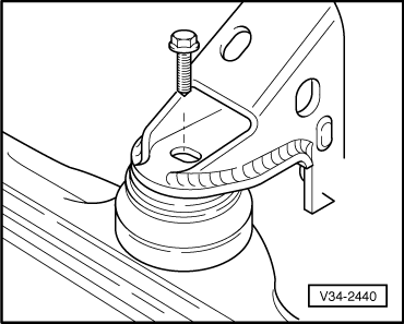
Gearboxes with clipped selector lever cable:

 
N37-0324
  • ‒ → Release selector lever cable first -1- then remove from support bracket -2-.
 
V37-1047
  • ‒ → Clamp-off ATF cooler hoses with -3094- and detach at ATF cooler.
 
V37-1046
  • ‒ → Fit support bar 10-222 A with legs 10-222 A/1 (6-cyl. engine adapter 10-222 A/3) and support engine/gearbox in this position.
 
N37-0058
  • ‒ → Remove vacuum pipe -a- and connector -b- before inserting support bar into eye (arrow) on vehicles with 6-cylinder engines.
  • ‒ Remove starter.
  • ‒ Remove bracket for power assisted steering pressure hose.
    • ‒ Pull connector off radiator fan motor on vehicles with 6-cylinder engine.
 
V34-2440
  • ‒ → Unscrew front console from engine carrier.
  • ‒ Remove console.
  • ‒ Unscrew coolant expansion tank and lay to one side.
  • ‒ Remove left engine mounting console complete.
  • ‒ Remove upper engine/gearbox connecting bolts.
    • ‒ On vehicles with 6-Cyl. engines mark connecting bolts .
  • ‒ Remove ATF oil pan protective plate.
    • ‒ Remove right-hand belt drive cover on vehicles with 6-cylinder engine.
  • ‒ Remove torque converter cover plate and nuts from torque converter.
    • ‒ Remove vibration damping weight on vehicles with 6-cylinder engine.
  • ‒ Disconnect drive shafts at flanges.
  • ‒ Raise right drive shaft and secure.
  • ‒ Remove left wheel.
 
V40-1311
  • ‒ Turn steering to right lock.
  • ‒ Mark installation position of ball joint bolts on left-hand wishbone and remove bolts.
    • ‒ → Vehicles with plus running gear, remove outer bolts and loosen inner bolts.
  • ‒ Swing ball joint outwards and place left-hand drive shaft to one side. Remove drive shaft with triple roller joint.

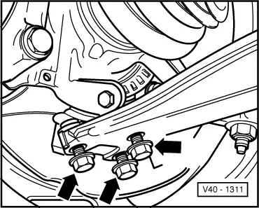
=> Running gear; Repair group 40; Removing and installing drive shafts.

 
V37-1049
  • ‒ → Set up gearbox support 3282.

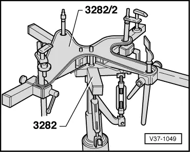
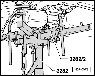
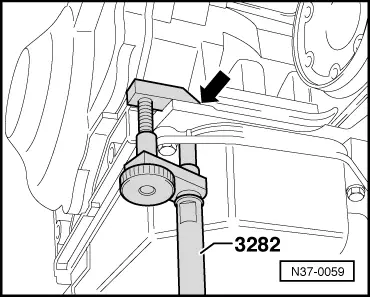
The gearbox support 3282 is set up with the adjusting plate 3282/2 for removing the automatic gearbox 01M.

The symbols on the adjusting plate indicate the supports required.

 
N37-0079
  • ‒ → Move jack V.A.G 1383 A with gearbox support 3282 under the gearbox and support gearbox.
 
N37-0059
  • ‒ → Place safety support pin on sump and secure to gearbox housing (arrow).
  • ‒ Remove lower engine/gearbox connecting bolts.
 
N37-0061
  • ‒ → Tilt engine and gearbox forwards with supporting device 3300 A.
  • ‒ Press gearbox off engine; when doing this, press torque converter out of drive plate.
  • ‒ Press torque converter against ATF pump.
  • ‒ Lower engine using support device spindle.
  • ‒ Lower gearbox slightly.
  • ‒ When doing this guide the power assisted steering pressure pipe past the gearbox.
  • ‒ Tilt gearbox using gearbox jack spindle and whilst lowering ensure cover (wheel housing side) is guided closely past wheel housing.
  • ‒ Swivel gearbox and carefully lower.

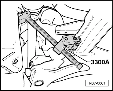
Ensure that the right joint flange does not contact the supporting device 3300 A and that the multi-function switch does not contact the subframe.

  • ‒ Secure torque converter to prevent it falling out.

Installing

Installation is performed in the reverse order.

  • ‒ Before installing the torque converter, observe sleeve bearing in turbine shaft .

When installing the torque converter, ensure that both drive pins engage in the ATF pump inner wheel recesses.

  • ‒ Before installing, ensure that the dowel sleeves are correctly located.
  • ‒ When installing gearbox, observe torque converter contact impression on drive plate.

Vehicles with 6-cyl. engine

If the gearbox has not been renewed:

  • ‒ Do not interchange upper engine/gearbox connecting bolts and install in the same position.
 
N37-0873

→ Flange thickness -arrow-: 55 mm

Pos.

Bolt

Nm

1

M 12 x 80

80

2

M 12 x 551)

80

3

M 12 x 58

80

4

M 12 x 46

80

52)

M 7 x 12

15

6

M 12 x 58

80

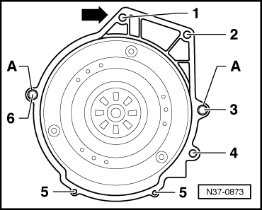
Pos. A = Dowel sleeves for centralising

     1)     Hexagon bolt with threaded shank M8 x 10

     2)     Cover plate to gearbox

When installing a new gearbox note the following:

When installing new gearboxes, special care must be taken regarding the length of the engine/gearbox connecting bolts.

New gearboxes have a flange thickness reduced by 25 mm -arrow- and modified connecting bolts.

 
N37-0873

→ Flange thickness -arrow-: 30 mm

Pos.

Bolt

Nm

11)

M 12 x 55

80

2

M 12 x 552)

80

3

M 12 x 55

80

4

M 12 x 55

80

53)

M 7 x 12

15

64)

M 12 x 65

80

Pos. A = Dowel sleeves for centralising

1)The cylinder block will be damaged if the bolt is too long when tightening.

     2)     Hexagon bolt with threaded pin M 8 x 10

     3)     Cover plate to gearbox

     4)     When tightening the thread in the gearbox will be damaged if the bolt is too short.

  • ‒ When installing a new gearbox with modified flange, modified bolts must be installed at Pos. 1, 4 and 6.

Continued for all vehicles

  • ‒ Replace selector cable anchorage locking washer.
  • ‒ Check selector lever cable adjustment, adjust if necessary => Page 37-3 .
  • ‒ Check and top up ATF level .
  • ‒ Perform self-diagnosis and initiate basic setting.

=> Self-diagnosis for automatic gearbox 01M - from 01.95; Repair group 01; Performing self-diagnosis

in booklet:

  • ◆ Workshop Manual Golf 1992 ▸, Vento 1992 ▸ Self-diagnosis for automatic gearbox 01M - from 01.95

Tightening torques

Drive shaft to flange

45 Nm

Torque converter to drive plate

60 Nm

Gearbox to engine bolt M 12

80 Nm

Gearbox to engine bolt M 10

60 Nm

Front console to assembly mounting

60 Nm

Console to left assembly mounting

60 Nm

Left console to gearbox

25 Nm

Cover plate to gearbox

15 Nm

Ball joint to wishbone

35 Nm

Starter to gearbox

60 Nm

Removing and installing starter bush > < Fault finding table for "4-speed automatic gearbox"