volkswagen Workshop Repair Guides

Volkswagen Workshop Service and Repair Manuals

Checking Lambda probe heating > < Performing basic setting
1AV fuel injection and ignition system
Servicing injection system
Checking Lambda probe and Lambda control

Special tools, testers, measuring instruments and auxiliary items required

  • ◆ Fault reader V.A.G 1551 or vehicle system tester V.A.G 1552 with cable V.A.G 1551/3
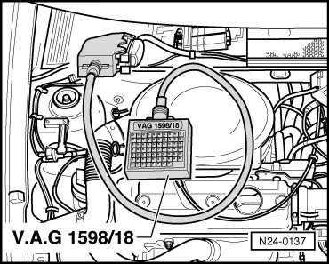
  • ◆ Test box V.A.G 1598/18
  • ◆ Hand multimeter V.A.G 1526 or multimeter V.A.G 1715
  • ◆ Adapter set V.A.G 1594
  • ◆ Current flow diagram

Check conditions

  • ● Basic setting OK.
  • ● Exhaust system between cylinder head and catalyst free of leaks

Test sequence

  • ‒ Connect fault reader V.A.G 1551 (V.A.G 1552). Start engine and select "Address word" 01 of engine control unit. When doing this the engine must be running at idling speed.
    (Connecting fault reader and selecting engine control unit .)
 
→ Indicated on display:
Rapid data transfer     HELP
Select function XX
  • ‒ Press keys 0 and 8 for the function "Read measured value block" and confirm entry with Q key.
 
→ Indicated on display:
Read measured value block     HELP
Input display group number XXX
  • ‒ Press keys 0, 0 and 1 for "Display group number 1" and confirm entry with Q key.
 
→ Indicated on display:
(1...4 = Display zones)
Read measured value block     1     ⇒
     1     2     3     4

Only continue with the test when

  • ● The coolant temperature is above 80 °C
    -Display zone 2-
  • ● The engine has then run for a further 2 minutes at idling speed
  • ‒ Note Lambda probe voltage in display zone 3. The voltage must
         fluctuate at least 30 times per minute
    in range of
         0... 1.0 V.

If the voltage change is slower, determine cause of fault. => Page 24-27 .

 
N24-0147
  • ‒ → Pull connector -1- off coolant temperature sender (G62) -2-. The probe voltage must
         increase
    and then decrease back to the old control range.
  • ‒ Reconnect connector. The probe voltage must
         decrease
    and then increase to the old control range.

Note:

The throttle valve must not be operated during the check, otherwise the connector disconnected from the control unit will be recognised as a fault.

  • ‒ Press ⇒ key.
 
N24-0137
  • ‒ Press keys 0 and 6 for the function "End output" and confirm entry with the Q key.
  • ‒ Switch off ignition

If no control is detected:

  • ‒ Check Lambda probe heating => Page 24-28 .
  • ‒ → Connect test box V.A.G 1598/18 to control unit wiring loom.
 
N24-0156
  • ‒ → Separate 4 pin connector to Lambda probe (G39) -1-.
  • ‒ Check wiring between test box and connector for open circuit according to current flow diagram.
         Contact 3+socket 15
         Contact 4+socket 38
         Wire resistance: Max. 1.5 ω
  • ‒ Check wiring at connector contacts 3+4 for short circuit to contacts 1+2 according to current flow diagram.
         Specification: ∞ω

If no wiring fault is detected:

  • ‒ Renew Lambda probe (G39) , item 23 .

Possible causes of fault if probe control frequency is too slow:

  • ◆ The slots or holes in probe body are blocked
  • ◆ The probe vent hole in area of connecting wire is blocked
  • ◆ The probe has been overheated (glazed)
  • ◆ The probe has been damaged by leaded fuel

Checking Lambda probe heating > < Performing basic setting