Golf Mk3
|
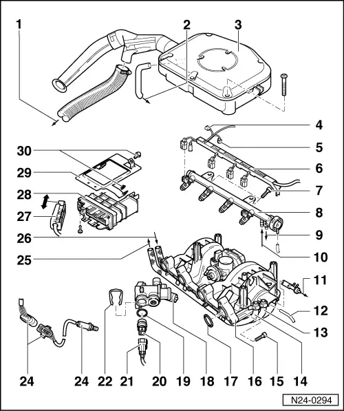
Servicing injection system
Removing and installing parts of the injection system
|
 |
|
|
|
|
|
|
|
|
|
|
|
|
|
|
|
|
|

|
Servicing injection system
Removing and installing parts of the injection system
|
|
|
|
|
|
|
|
|
|
|
|
|
|
|
|
|
|
|