volkswagen Workshop Repair Guides

Volkswagen Workshop Service and Repair Manuals

Reworking valve seats > < Removing and installing cylinder head
4-Cyl. diesel engine, Mechanics
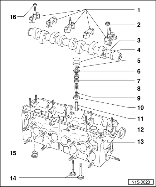
Servicing valve gear
 
N15-0023

Note:

Cylinder heads with cracks between the valve seats may be used without reducing engine life, provided the cracks are small and not more than 0.5 mm wide.

  • Bearing cap
    • ◆ Installation position => Fig. 2
    • ◆ Installation sequence
      , removing and installing camshaft
  • 20 Nm
 
N15-0023
  • Camshaft
    • ◆ Checking axial clearance => Fig. 1
    • ◆ Removing and installing
      => Page 15-31
    • ◆ Checking radial clearance with plastigage
           Wear limit: 0.11 mm
    • ◆ Run-out: max. 0.01 mm
    • ◆ Identification and valve timing
      => Fig. 4
  • Bucket tappet
    • ◆ Do not interchange
    • ◆ With hydraulic valve clearance compensation
    • ◆ Checking => Page 15-33
    • ◆ Store with cam lobe contact surface downwards
    • ◆ Before installing check camshaft axial clearance => Fig. 1
    • ◆ Oil contact surface
  • Cotters
 
N15-0023
  • Upper valve spring plate
  • Valve spring
    • ◆ 10.94▸only one-part valve spring
    • ◆ Removing and installing:
      Cylinder head
      removed: with 2037
      installed: => Page 15-29 , renewing valve stem seals
  • Inner valve spring
    • ◆ ▸09.94
    • ◆ Removing and installing:
      Cylinder head
      removed: with 2037
      installed: => Page 15-29 , renewing valve stem seals
  • Valve stem seal
  • Lower valve spring plate
    • ◆ Remove and install with 3047A
    • ◆ ▸09.94
 
N15-0023
  • Valve guide
    • ◆ Checking => Page 15-27
    • ◆ Renewing => Page 15-27
    • ◆ Service version with collar
  • Oil seal
    • ◆ To remove and install, remove bearing cap
    • ◆ Removing and installing toothed belt
  • Cylinder head
    • ◆ See note
      => Page 15-16
    • ◆ Reworking valve seats
      => Page 15-24
  • Valves
    • ◆ Valve dimensions => Fig. 3
  • Swirl chamber
    • ◆ Engine codes
      1Z, AAZ
    • ◆ Renew if damaged
    • ◆ Renewing => Page 15-35
  • Lower sealing cone
 
V15-0456

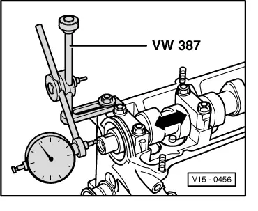
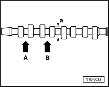
→ Fig. 1     Checking camshaft axial clearance

Wear limit: max. 0.15 mm

Check with bucket tappets removed and with first and last bearing caps fitted.

 
V15-0098

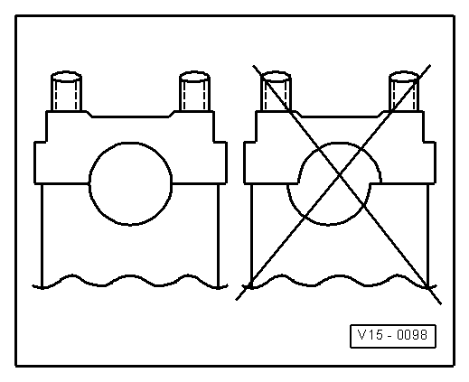
→ Fig. 2     Fitting position of camshaft bearing caps

Note offset. Before installing camshaft fit bearing caps and determine fitting position.

 
V15-0024

→ Fig. 3     Valve dimensions

Note:

Valves must not be reworked. Only lapping-in is permitted.

Engine codes 1Z, AHU, AEY, AFN, AVG, ALE

Dimension

Inlet valve

Exhaust valve

øa

mm

35.95

31.45

øb

mm

▸06.95: 7.97
07.95 ▸: 6.97

▸06.95: 7.95
07.95 ▸: 6.95

c

mm

AEY: 96.35
1Z, AHU, AFN, AVG,ALE:96.85

AEY: 96.35
1Z, AHU, AFN, AVG,ALE:96.85

α

45

45

Engine codes 1Y, AAZ

Dimension

Inlet valve

Exhaust valve

øa

mm

36.0

31.0

øb

mm

▸06.95: 7.97
07.95 ▸: 6.97

▸06.95: 7.95
07.95 ▸: 6.95

c

mm

95.0

95.0

α

45

45

 
N15-0022

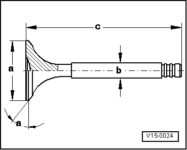
→ Fig.4     Camshaft identification, valve timing

Identification

  • ◆ Cam base diameter: a = 38 mm ø
  • ◆ Identification by stamped numbers and letters between inlet and exhaust cams:

Engine code

1Y

1Z

AAZ

AEY

AFN

AHU

ALE

AVG

Cylinder 1 -arrow A-

W

W

W

W

W

W

W

W

Cylinder 2 -arrow B-

028
D

028
F

028
D

028
E

028
F

028
F

028
F

028
F

Valve timing at 1 mm valve lift

Engine code

1Y

1Z

AAZ

AEY

AFN

AHU

ALE

AVG

Inlet opens after TDC

6 °

16 °

6 °

11 °

16 °

16 °

16 °

16 °

Inlet closes after BDC

20 °

25 °

20 °

25 °

25 °

25 °

25 °

25 °

Exhaust opens before BDC

25.5 °

28 °

25.5 °

40 °

28 °

28 °

28 °

28 °

Exhaust closes before TDC

6.5 °

19 °

6.5 °

10 °

19 °

19 °

19 °

19 °

Reworking valve seats > < Removing and installing cylinder head