volkswagen Workshop Repair Guides

Volkswagen Workshop Service and Repair Manuals

Piston and cylinder dimensions > < Crankshaft dimensions
4-Cyl. injection engine (4-valve), Mechanics
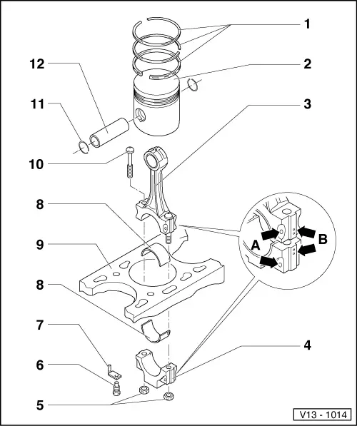
Dismantling and assembling pistons and conrods
 
V13-1014
  • Piston ring
    • ◆ Offset gaps by 120 °
    • ◆ Remove and install with piston ring pliers
    • ◆ "TOP" faces towards piston crown
    • ◆ Checking ring gap=> Fig. 1
    • ◆ Checking ring to groove clearance
      => Fig. 2
  • Piston
    • ◆ Checking => Fig. 3
    • ◆ Mark installation position and cylinder number
    • ◆ Arrow on piston crown points to pulley end
    • ◆ Install using piston ring clamp
 
V13-1014
  • Conrod
    • ◆ Only renew as a set
    • ◆ Mark cylinder number -B-
    • ◆ Installation position:
      Marking -A- faces towards pulley end
    • ◆ With oil drilling for piston pin lubrication
  • Conrod bearing cap
    • ◆ Note installation position
  • 30 Nm + 1/4 turn (90 °) further
    • ◆ Oil threads and contact surface
    • ◆ To measure radial clearance tighten to 30 Nm but not further
  • Pressure relief valve, 27 Nm
    • ◆ Opening pressure: 2.5...3.2 bar
 
V13-1014
  • Oil spray jet
    • ◆ For piston cooling
  • Bearing shell
    • ◆ Note installation position
    • ◆ Do not interchange used bearing shells
    • ◆ Ensure retaining lugs fit tightly in recesses
    • ◆ Axial clearance
      New: 0.05...0.31 mm
      Wear limit: 0.37 mm
    • ◆ Check radial clearance with Plastigage:
      New: 0.01...0.06 mm
      Wear limit: 0.12 mm
      Do not rotate crankshaft when checking radial clearance
    • ◆ With oil drilling for piston pin lubrication
  • Cylinder block
    • ◆ Checking cylinder bores
      =>Fig. 4
    • ◆ Piston and cylinder dimensions
 
V13-1014
  • Conrod bolt
  • Circlip
  • Piston pin
    • ◆ If difficult to remove, heat piston to 60 °C
    • ◆ Remove and install with VW 222a
 
V13-0016

→ Fig. 1     Checking piston ring gap

  • ‒ Push ring squarely from above down to approx. 15 mm from bottom end of cylinder.

Piston ring

Gap

New

Wear
limit

Compression rings

mm

0.20...0.40

1.0

Oil scraper ring

mm

0.25...0.50

1.0

 
V13-0687

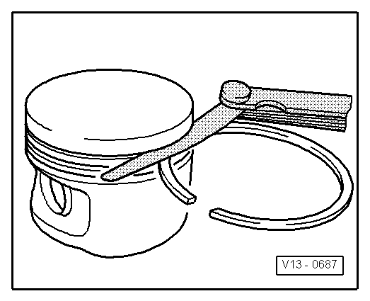
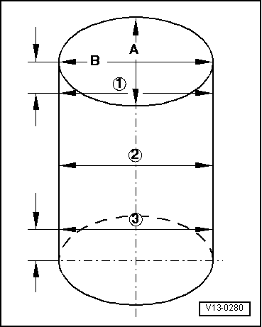
→ Fig. 2     Checking ring to groove clearance

Clean groove before check.

Piston ring

Clearance

New

Wear
limit

Compression rings

mm

0.02...0.07

0.15

Oil scraper ring

mm

0.02...0.06

0.15

 
V13-0010

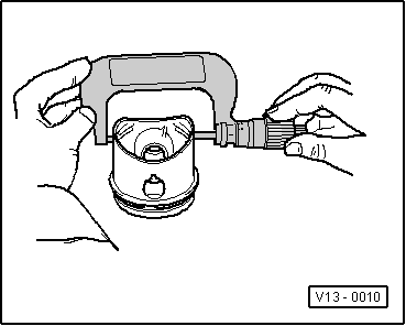
→ Fig. 3     Checking piston

Special tools, testers and auxiliary items

  • ◆ Micrometer 75...100 mm
  • ‒ Approx. 10 mm from lower edge and offset 90 ° to piston pin axis. Deviations from nominal dimensions
         max. 0.04 mm
  • Nominal dimension ; Piston and cylinder dimensions
 
V13-0280

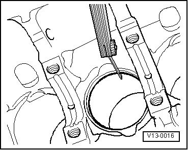
→ Fig. 4     Checking cylinder bores

Special tools, testers and auxiliary items

  • ◆ Internal dial gauge 50...100 mm
  • ‒ Take measurements at 3 positions in both lateral -A- and longitudinal -B- directions, as illustrated. Deviation from nominal dimension
         max. 0.08 mm
  • Nominal dimension => Page 13-34 ; Piston and cylinder dimensions

Note:

Measuring the cylinder bores must not be done when the cylinder block is mounted on a repair stand with adapter bracket VW 540, as incorrect measurements would then be possible.

Piston and cylinder dimensions > < Crankshaft dimensions