Golf Mk3
|
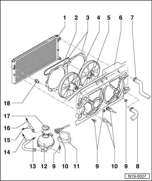
Removing and installing parts of cooling system
Parts of cooling system body side
|
 |
|
|
Engine codes AEK, AFT, AKS
|
|
|
 |
|
|
Engine codes ATU, AWF, AWG |
|
|
|
|
|
|

|
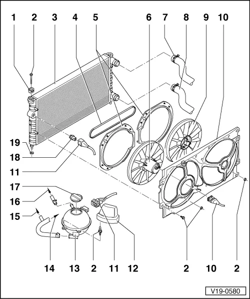
Removing and installing parts of cooling system
Parts of cooling system body side
|
|
|
|
Engine codes AEK, AFT, AKS
|
|
|
|
|
|
Engine codes ATU, AWF, AWG |
|
|
|
|
|
|