volkswagen Workshop Repair Guides

Volkswagen Workshop Service and Repair Manuals

Checking coolant temperature sender > < Checking engine speed sender
Diesel direct injection and glow plug system
Checking components and functions
Checking intake manifold pressure sender and elevation sender

(Engine codes AFN, AVG, AHU, ALE, 1Z only)

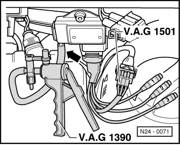
Both pressure senders are located in the Diesel direct injection system control unit. Only for vehicles up to 08.94the altitude sender -F96is a separate component and is located behind dash panel above central electrics.

Special tools, workshop equipment, testers, measuring instruments and auxiliary items required

  • ◆ Fault reader V.A.G 1551 or vehicle system tester V.A.G 1552 with cable V.A.G 1551/3
  • ◆ Test box V.A.G 1598/18
  • ◆ Hand multimeter V.A.G 1526 or multimeter V.A.G 1715
  • ◆ Measuring cable V.A.G 1501
  • ◆ Adapter set V.A.G 1594
  • ◆ Current flow diagram

Test sequence

  • ‒ Connect the fault reader V.A.G 1551 (V.A.G 1552). Then switch ignition on and select engine control unit with the "Address word" 01.
    (Connecting fault reader and selecting engine control unit .)
 
→ Indicated on display:
Rapid data transfer     HELP
Select function XX
  • ‒ Press keys 0 and 8 for the function "Read measured value block" and confirm entry with Q key.
 
→ Indicated on display:
Read measured value block     HELP
Input display group number XXX
  • ‒ Press keys 0, 1 and 0 for "Display group number 10" and confirm entry with Q key.
 
→ Indicated on display:
Read measured value block 10     ⇒
0 mg/H     1027 mbar     1013 mbar     0 %
  • ‒ Compare display in display zone 2 (altitude sender -F96) and display zone 3 (intake manifold pressure sender -G71).

Specification: Pressures the same
     (Tolerance ±30 mbar)

  • ‒ If specification is not attained, compare displayed pressures with a barometer (e.g. Turbocharger tester V.A.G 1397/A), tolerance ±30 mbar:
    • ‒ If figure in display zone 3 is not correct, pull pressure hose off control unit.
    • ‒ If figure in display zone 3 is not correct, renew diesel direct injection control unit.
    • ‒ If the figure in display zone 2 is not correct and a constant figure of 695 or 1024 mbar is displayed:

On vehicles from 08.94:

  • ‒ Renew Diesel direct injection system control unit (J248) => Page 23-118 .

On vehicles up to 08.94:

    • ‒ Check altitude sender as described below.
  • Disconnect connector for altitude sender (F96) =>Fitting locations overview, Page 23-4 .
 
N24-0071
  • ‒ → Connect cable V.A.G 1501 to sender (F96) and connector.
  • ‒ Connect vacuum pump V.A.G 1390 to altitude sender (F96) -arrow-.
  • ‒ Switch on ignition.
  • ‒ Select measuring range 20 V on hand multimeter V.A.G 1526 and connect to cable test sockets 1 + 2.
         Specification: approx. 5 V
  • ‒ Connect hand multimeter V.A.G 1526 to cable test sockets 2 + 3.
         Specification: approx. 4.5 V
  • ‒ Operate vacuum pump,
         Voltage must decrease.
  • ‒ If the voltage does not decrease, replace altitude sender (F96).

Checking wiring connection to altitude sender (F96)

  • ‒ Switch off ignition.
  • ‒ Disconnect connector for altitude sender =>Fitting locations overview, Page 23-4 .
  • ‒ Connect test box =>Page23-43 .
 
V96-0836
  • ‒ → Check wiring between test box and 3 pin connector for open circuit using current flow diagram.
         Contact 1+ socket 41
         Contact 2+ socket 33
         Contact 3+ socket 40
         Wire resistance: max. 1.5 ω
  • ‒ Check wiring at 3 pin connector for short circuit to one another according to current flow diagram.
         Specification: ∞ω

If no wiring fault is detected:

  • ‒ Renew Diesel direct injection system control unit (J248) => Page 23-118 .

Checking coolant temperature sender > < Checking engine speed sender