◆ Hand multimeter V.A.G 1526 or multimeter V.A.G 1715
◆ Adapter set V.A.G 1594
◆ Current flow diagram
Test conditions
● Fault on one or both knock sensors recognised by self-diagnosis
● Fault memory erased
Test sequence
‒ →
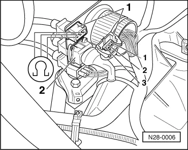
Detach brown 3 pin connector to knock sensor 1 (G61) -1- or black 3 pin connector to knock sensor 2 (G66) -2-.
‒ Measure resistance between the contacts 1+2, 1+3 and 2+3 at connection to knock sensor.
Specification ∞ω
‒ →
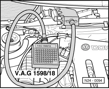
Connect test box V.A.G 1598/18 to control unit wiring loom.
‒ Check wiring between test box and 3 pin connector for open circuit according to current flow diagram.
G61:
G66:
Contact 1+socket
34
57
Contact 2+socket
32
56
Contact 3+socket
10
55
Wire resistance: Max. 1.5 ω
‒ Additionally check wires for short to one another.
Specification: ∞ω
If no wiring fault is detected:
‒ Loosen knock sensor and tighten again to 20 Nm.
If the fault is still present (fault again in fault memory):