volkswagen Workshop Repair Guides

Volkswagen Workshop Service and Repair Manuals

Checking fuel pressure regulator and holding pressure > < Checking starter signal
Digifant injection and ignition system (4-valve)
Digifant injection and ignition system
Checking injectors

Checking activation

Special tools, testers and auxiliary items

  • ◆ Test box V.A.G 1598/18
  • ◆ Hand multimeter V.A.G 1526 or multimeter V.A.G 1715
  • ◆ Diode test lamp V.A.G 1527
  • ◆ Adapter set V.A.G 1594
  • ◆ Current flow diagram

Check conditions

  • ● Engine speed sender OK.
 
N24-0107
  • ● Fuel pump relay OK

Test sequence

  • ‒ → Pull plug -1- off connection -2- and connect diode test lamp V.A.G 1527 with aux. cables from V.A.G 1594 to the contacts 1+5 of the plug.
  • ‒ Operate starter.
         The LED must flash
  • ‒ Repeat check on contacts 2+5, 3+5 and 4+5.

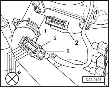
The LED does not flicker:

  • ‒ Switch off ignition.
 
N24-0094
  • ‒ → Connect test box V.A.G 1598/18 to control unit wiring loom.
  • ‒ Check wiring between test box and 5 pin connector for open circuit according to current flow diagram.
         Contact 1+socket 24
         Contact 2+socket 25
         Contact 3+socket 26
         Contact 4+socket 2
         Wire resistance: Max.1.5 ω
  • ‒ Check wire between 5 pin connector contact 5 and relay plate for open circuit according to current flow diagram.
         Wire resistance: Max. 1.5 ω
  • ‒ Additionally check wires for short to one another.
         Specification: ∞ω

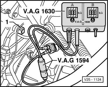
Checking resistance of injectors with wiring

 
N24-0108
  • ‒ Check individual injector resistance with hand multimeter V.A.G 1526 on the contacts of the connector -2-.

Injector

1

2

3

4

Contacts

1+5

2+5

3+5

4+5

  •      Specification: 15...20 ω

If the specification is not attained:

  • ‒ Remove intake manifold upper part.
Warning!
The fuel system is pressurized! Before loosening hose connections or opening the test connection, wrap a cloth around the connection. Then release pressure by carefully pulling off the hose/sealing cap.

  • ‒ Remove fuel manifold, dismantle and repeat check on the injectors individually, if necessary renew injector(s).

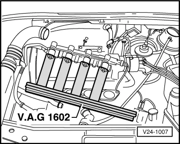
Checking spray pattern and for leaks

Special tools, testers and auxiliary items

  • ◆ Adapter set V.A.G 1594
 
V25-1124
  • ◆ Digital potentiometer V.A.G 1630
  • ◆ Measuring unit V.A.G 1602

Test sequence

  • ‒ → Pull plug off coolant temperature sender (G62).
  • ‒ Set digital potentiometer V.A.G 1630 -side A- to 15 kωand using aux. cables from V.A.G 1594 connect to disconnected plug.
  • ‒ Remove intake manifold upper part.
 
V24-1007
  • ‒ Pull 5 pin connector out of retainer and remove wiring from clips.
  • ‒ Remove fuel distributor (fuel hoses remain connected).
  • ‒ → Hold injectors in the measuring appliance V.A.G 1602.
  • ‒ Pull plug off ignition transformer.
  • ‒ Operate starter (2nd person required). The injectors must pulsate and spray in accordance with firing order.
  • ‒ Switch off ignition and check injectors for leaks. No more than
         2 drops/min
    may leak from each injector.

Note:

When installing the injectors ensure that the O rings

are not damaged.

Checking fuel pressure regulator and holding pressure > < Checking starter signal